Dodge Caliber. Manual - part 842


  Index      Dodge     Dodge Caliber - service repair manual 2007 year


Search            


Content   ..  840  841  842  843   ..


Dodge Caliber. Manual - part 842


6.

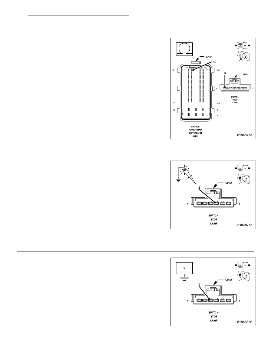
(B15) BRAKE SIGNAL 1 CIRCUIT OPEN OR HIGH RESISTANCE

Measure the resistance of the (B15) Brake Signal 1 circuit between the
Stop Lamp Switch harness connector and the Powertrain Control Mod-
ule (PCM) harness connector.

Is the resistance below 5.0 ohms?

Yes

>> Go to 10

No

>> Repair the (B15) Brake Signal 1 circuit for an open circuit or

high resistance.

Perform the PCM Verification Test Ver. 1 (Refer to 9 -
ENGINE - DIAGNOSIS AND TESTING).

7.

(F202) FUSED IGNITION SWITCH OUTPUT (RUN-START) CIRCUIT OPEN OR HIGH RESISTANCE

Turn the ignition off.

Disconnect the Stop Lamp Switch connector.

Turn the ignition on.

Using a 12 volt test light connected to ground, check the (F202) Fused
Ignition Switch Output (Run-Start) circuit in the Stop Lamp Switch har-
ness connector.

NOTE: The test light should be illuminated and bright. Compare
the brightness to that of a direct connection to the battery.

Is the test light illuminated and bright?

Yes

>> Go to 8

No

>> Repair the (F202) Fused Ignition Switch Output (Run-Start)

circuit for an open circuit or high resistance.

Perform the PCM Verification Test Ver. 1 (Refer to 9 - ENGINE - DIAGNOSIS AND TESTING).

8.

(B16) BRAKE SIGNAL 2 CIRCUIT SHORTED TO VOLTAGE

Measure the voltage of the (B16) Brake Signal 2 circuit in the Stop
Lamp Switch harness connector.

Is there any voltage present?

Yes

>> Repair the (B16) Brake Signal 2 circuit for a short to volt-

age.

Perform the PCM Verification Test Ver. 1 (Refer to 9 -
ENGINE - DIAGNOSIS AND TESTING).

No

>> Go to 9

PM

ENGINE ELECTRICAL DIAGNOSTICS - GPEC

9 - 655

9.

(B16) BRAKE SIGNAL 2 CIRCUIT OPEN OR HIGH RESISTANCE

Measure the resistance of the (B16) Brake Signal 2 circuit between the
Stop Lamp Switch harness connector and the Powertrain Control Mod-
ule (PCM) harness connector.

Is the resistance below 5.0 ohms?

Yes

>> Go to 10

No

>> Repair the (B16) Brake Signal 2 circuit for an open circuit or

high resistance.

Perform the PCM Verification Test Ver. 1 (Refer to 9 -
ENGINE - DIAGNOSIS AND TESTING).

10.

STOP LAMP SWITCH

Using the wiring diagram/schematic as a guide, inspect the wiring and connectors between the Stop Lamp Switch
and the Powertrain Control Module (PCM).

Look for any chafed, pierced, pinched, or partially broken wires.

Look for broken, bent, pushed out or corroded terminals.

Refer to any Technical Service Bulletins that may apply.

Were any problems found?

Yes

>> Repair as necessary.

Perform the PCM Verification Test Ver. 1 (Refer to 9 - ENGINE - DIAGNOSIS AND TESTING).

No

>> Replace the Stop Lamp Switch in accordance with the Service Information.

Perform the PCM Verification Test Ver. 1 (Refer to 9 - ENGINE - DIAGNOSIS AND TESTING).

11.

POWERTRAIN CONTROL MODULE (PCM)

Using the wiring diagram/schematic as a guide, inspect the wiring and connectors between the Stop Lamp Switch
and the Powertrain Control Module (PCM).

Look for any chafed, pierced, pinched, or partially broken wires.

Look for broken, bent, pushed out or corroded terminals.

Refer to any Technical Service Bulletins that may apply.

Were any problems found?

Yes

>> Repair as necessary.

Perform the PCM Verification Test Ver. 1 (Refer to 9 - ENGINE - DIAGNOSIS AND TESTING).

No

>> Replace and program the Powertrain Control Module (PCM) in accordance with the Service Information.

Perform the PCM Verification Test Ver. 1 (Refer to 9 - ENGINE - DIAGNOSIS AND TESTING).

9 - 656

ENGINE ELECTRICAL DIAGNOSTICS - GPEC

PM

P1593-SPEED CONTROL SWITCH 1/2 STUCK

For a complete wiring diagram Refer to Section 8W

When Monitored:
With the ignition on and battery voltage greater than 10.4 volts.

Set Condition:
The ECM detects that the (V71) S/C Signal 1 voltage does not match the (V72) S/C Signal 2 voltage.

Possible Causes

INTERMITTENT DTC

(V71) S/C SIGNAL 1 CIRCUIT SHORTED TO VOLTAGE

(V72) S/C SIGNAL 2 CIRCUIT SHORTED TO VOLTAGE

(V71) S/C SIGNAL 1 CIRCUIT SHORTED TO GROUND

(V72) S/C SIGNAL 2 CIRCUIT SHORTED TO GROUND

(V71) S/C SIGNAL 1 CIRCUIT SHORTED TO THE (V937) S/C SWITCH GROUND CIRCUIT

(V72) S/C SIGNAL 2 CIRCUIT SHORTED TO THE (V937) S/C SWITCH GROUND CIRCUIT

(V71) S/C SIGNAL 1 CIRCUIT OPEN OR HIGH RESISTANCE

(V72) S/C SIGNAL 2 CIRCUIT OPEN OR HIGH RESISTANCE

(V937) S/C SWITCH GROUND CIRCUIT OPEN OR HIGH RESISTANCE

CLOCKSPRING

SPEED CONTROL SWITCH

STEERING CONTROL MODULE (SCM)

POWERTRAIN CONTROL MODULE (PCM)

Always perform the Pre-Diagnostic Troubleshooting procedure before proceeding. (Refer to 9 - ENGINE -
DIAGNOSIS AND TESTING)

Diagnostic Test

1.

DTC IS ACTIVE

Turn the ignition on.

With a scan tool, select View DTCs.

Is the status Active for this DTC?

Yes

>> Go to 2

No

>> Refer to the *CHECKING FOR AN INTERMITTENT DTC Diagnostic Procedure. (Refer to 9 - ENGINE -

DIAGNOSIS AND TESTING)

2.

SPEED CONTROL SWITCH

Turn the ignition off.

Remove the Speed Control Switch in accordance with the Service Information.

Turn the ignition on.

With a scan tool, read the (V71) S/C Signal 1 and (V72) S/C Signal 2 voltages.

NOTE: The voltages should be above 4.8 volts with the Speed Control Switch connector disconnected.
Connect a jumper wire between the (V71) S/C Signal 1 circuit and the (V937) S/C Switch Ground circuit in the
Speed Control Switch harness connector.

With a scan tool, read the (V71) S/C Signal 1 voltage.

NOTE: The (V71) S/C Signal 1 voltage should be below .2 volts with the jumper wire in place.
Connect a jumper wire between the (V72) S/C Signal 2 circuit and the (V937) S/C Switch Ground circuit in the
Speed Control Switch harness connector.

With a scan tool, read the (V72) S/C Signal 2 voltage.

PM

ENGINE ELECTRICAL DIAGNOSTICS - GPEC

9 - 657

NOTE: The (V72) S/C Signal 2 voltage should be below .2 volts with the jumper wire in place.

Are the Speed Control voltages displayed as described?

Yes

>> Replace the Speed Control Switch in accordance with the Service Information.

Perform the PCM Verification Test Ver. 1 (Refer to 9 - ENGINE - DIAGNOSIS AND TESTING).

No

>> Go to 3

3.

CLOCKSPRING

Turn the ignition off.

Disconnect the Steering Control Module (SCM) C5 harness connector.

Turn the ignition on.

With a scan tool, read the (V71) S/C Signal 1 and (V72) S/C Signal 2 voltages.

NOTE: The voltages should be above 4.8 volts with the Steering Control Module (SCM) C5 connector dis-
connected.
Connect a jumper wire between the (V71) S/C Signal 1 circuit and the (V937) S/C Switch Ground circuit at the
Steering Control Module (SCM) C5 connector, not at the harness connector.

With a scan tool, read the (V71) S/C Signal 1 voltage.

NOTE: The (V71) S/C Signal 1 voltage should be below .2 volts with the jumper wire in place.
Connect a jumper wire between the (V72) S/C Signal 2 circuit and the (V937) S/C Switch Ground circuit at the
Steering Control Module (SCM) C5 connector, not at the harness connector.

With a scan tool, read the (V72) S/C Signal 2 voltage.

NOTE: The (V72) S/C Signal 2 voltage should be below .2 volts with the jumper wire in place.

Are the Speed Control voltages displayed as described?

Yes

>> Replace the Clockspring in accordance with the Service Information.

Perform the PCM Verification Test Ver. 1 (Refer to 9 - ENGINE - DIAGNOSIS AND TESTING).

No

>> Go to 4

4.

STEERING CONTROL MODULE (SCM)

Turn the ignition off.

Disconnect the Steering Control Module (SCM) C2 connector.

Turn the ignition on.

With a scan tool, read the (V71) S/C Signal 1 and (V72) S/C Signal 2 voltages.

NOTE: The voltages should be above 4.8 volts with the connector disconnected.
Connect a jumper wire between the (V71) S/C Signal 1 circuit and the (V937) S/C Switch Ground circuit in the
Steering Control Module (SCM) C2 harness connector.

With a scan tool, read the (V71) S/C Signal 1 voltage.

NOTE: The (V71) S/C Signal 1 voltage should be below .2 volts with the jumper wire in place.
Connect a jumper wire between the (V72) S/C Signal 2 circuit and the (V937) S/C Switch Ground circuit in the
Steering Control Module (SCM) C2 harness connector.

With a scan tool, read the (V72) S/C Signal 2 voltage.

NOTE: The (V72) S/C Signal 2 voltage should be below .2 volts with the jumper wire in place.

Are the Speed Control voltages displayed as described?

Yes

>> Replace the Steering Control Module (SCM) in accordance with the Service Information.

Perform the PCM Verification Test Ver. 1 (Refer to 9 - ENGINE - DIAGNOSIS AND TESTING).

No

>> Go to 5

9 - 658

ENGINE ELECTRICAL DIAGNOSTICS - GPEC

PM


Content   ..  840  841  842  843   ..