Dodge Caliber. Manual - part 769


  Index      Dodge     Dodge Caliber - service repair manual 2007 year


Search            


Content   ..  767  768  769  770   ..


Dodge Caliber. Manual - part 769


7.

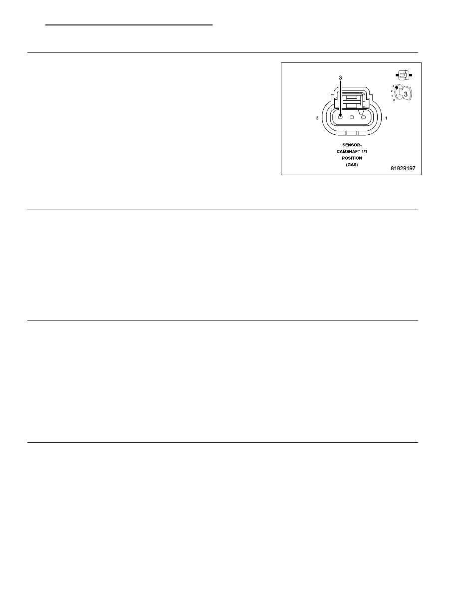
CAMSHAFT 1/1 POSITION SENSOR IRREGULAR SIGNAL

Using a lab scope and the Miller special tool #6801, backprobe the
(K44) CMP 1/1 Signal circuit in the Camshaft 1/1 Position Sensor har-
ness connector.

Ignition on, engine not running.

Wiggle the related wire harness and lightly tap on the Camshaft 1/1
Position Sensor while monitoring the lab scope screen.

Start the engine.

Monitor the Camshaft 1/1 Position Sensor signal on the lab scope
screen.

Were any Camshaft 1/1 Position Sensor signals irregular or
missing?

Yes

>> Go to 8

No

>> Go to 10

8.

CAMSHAFT 1/1, TONE WHEEL OR FLEX PLATE

Turn the ignition off.

Remove the Camshaft 1/1 Position Sensor.

Inspect the Camshaft 1/1 Position Sensor and mounting area for any condition that would result in an incorrect
signal, such as damage, foreign material, or excessive movement.

Were any problems found?

Yes

>> Repair as necessary in accordance with the Service Information.

Perform the PCM Verification Test Ver. 1 (Refer to 9 - ENGINE - DIAGNOSIS AND TESTING).

No

>> Go to 9

9.

CAMSHAFT 1/1 POSITION SENSOR

Using the wiring diagram/schematic as a guide, inspect the wiring and connectors between the Camshaft 1/1 Posi-
tion Sensor and the Powertrain Control Module (PCM).

Look for any chafed, pierced, pinched, or partially broken wires.

Look for broken, bent, pushed out or corroded terminals.

Were any problems found?

Yes

>> Repair as necessary.

Perform the PCM Verification Test Ver. 1 (Refer to 9 - ENGINE - DIAGNOSIS AND TESTING).

No

>> Replace the Camshaft 1/1 Position Sensor.

Perform the PCM Verification Test Ver. 1 (Refer to 9 - ENGINE - DIAGNOSIS AND TESTING).

10.

POWERTRAIN CONTROL MODULE (PCM)

Using the wiring diagram/schematic as a guide, inspect the wiring and connectors between the Camshaft 1/2 Posi-
tion Sensor and the Powertrain Control Module (PCM).

Look for any chafed, pierced, pinched, or partially broken wires.

Look for broken, bent, pushed out or corroded terminals.

Refer to any Technical Service Bulletins that may apply.

Were any problems found?

Yes

>> Repair as necessary.

Perform the PCM Verification Test Ver. 1 (Refer to 9 - ENGINE - DIAGNOSIS AND TESTING).

No

>> Replace and program the Powertrain Control Module (PCM) in accordance with the Service Information.

Perform the PCM Verification Test Ver. 1 (Refer to 9 - ENGINE - DIAGNOSIS AND TESTING).

PM

ENGINE ELECTRICAL DIAGNOSTICS - GPEC

9 - 363

P0420-CATALYST 1/1 EFFICIENCY

For a complete wiring diagram Refer to Section 8W.

When Monitored:
After engine warm up, at medium throttle with vehicle speed between 35 and 60 mph.

Set Condition:
If the switch rate of the downstream O2 sensor is within the calibrated fail threshold during monitoring. Two trip
fault. Three good trips to turn off the MIL.

Possible Causes

EXHAUST LEAK

ENGINE MECHANICAL CONDITION

AGING O2 SENSOR

CATALYTIC CONVERTER

Always perform the Pre-Diagnostic Troubleshooting procedure before proceeding. (Refer to 9 - ENGINE -
DIAGNOSIS AND TESTING).

Diagnostic Test

1.

EXHAUST LEAK

NOTE: A thorough exhaust leak test must be completed before removing an O2 Sensor or any other part
from the exhaust system. Do not remove any parts before an exhaust leak check has been completed.

NOTE: An exhaust leak may cause downstream fuel adaptives to rail out, resulting in a false O2 Sensor
failure
Turn the ignition off.

Inspect the exhaust system for leaks between the engine and the 1/1 Oxygen Sensor.

Inspect the exhaust system for leaks between the engine and within 6 inches downstream of the 1/2 Oxygen Sen-
sor.

Perform a leak test with Miller Tool #8404A Evaporative Emissions Leak Detector (EELD), even if an audible leak is
not heard. Pay particular attention to the exhaust manifold to head surface, exhaust pipe to manifold connection,
and the O2 sensor boss for leaks.

Connect the SMOKE supply tip (black hose) to the exhaust cone adapter (if equipped) and place it into the tail pipe.

Set the smoke/air control switch to SMOKE.

Press the remote smoke/air start button.

While still holding the remote smoke/air start button, use the white light (#8404-CLL) to follow the exhaust system
path and look for a leak, indicated by exiting smoke.

If a leak is concealed from view, release the remote smoke/air start button, and use the ultraviolet (UV) black light
#8404-UVL and the yellow goggles 8404-20 to look for residual traces of dye that is left behind by the smoke.

The exiting smoke deposits a residual fluid that is either bright green or bright yellow in color when viewed with a
UV light.

Were any exhaust leaks found?

Yes

>> Repair as necessary.

Perform the PCM Verification Test Ver. 1 (Refer to 9 - ENGINE - DIAGNOSIS AND TESTING).

No

>> Go to 2

9 - 364

ENGINE ELECTRICAL DIAGNOSTICS - GPEC

PM

2.

ACTIVE DTC

NOTE: A new downstream O2 Sensor and an aging upstream O2 Sensor may cause the DTC to set. Review
the repair history of the vehicle before continuing.

NOTE: If an O2 Sensor DTC is set along with the Catalytic Converter Efficiency DTC, diagnose the O2 Sen-
sor DTC(s) before continuing.

NOTE: Check for contaminants that may have damaged the O2 Sensor and Catalytic Converter: contami-
nated fuel, unapproved silicone, oil and coolant, repair necessary.

NOTE: It may be necessary to test drive the vehicle within the DTC monitoring conditions in order for this
DTC to set.
Start the engine and allow it to reach operating temperature.

WARNING: When the engine is operating, do not stand in direct line with the fan. Do not put your hands
near the pulleys, belts, or fan. Do not wear loose clothing. Failure to follow these instructions can result in
personal injury or death.
With a scan tool, select View DTCs.

Is the status Active for this DTC?

Yes

>> Go to 3

No

>> Refer to the *CHECKING FOR AN INTERMITTENT DTC Diagnostic Procedure. (Refer to 9 - ENGINE -

DIAGNOSIS AND TESTING)

3.

CATALYTIC CONVERTER INSPECTION

NOTE: Thoroughly inspect the top and bottom of the Catalytic Converter.
Inspect the Catalytic Converter for the following:

— Damage including dents, holes, internal damage, or leaks.

— Severe discoloration caused by overheating.

Were any problems found?

Yes

>> Replace the Catalytic Converter. If necessary, repair the condition that may have caused the failure.

Perform the PCM Verification Test Ver. 1 (Refer to 9 - ENGINE - DIAGNOSIS AND TESTING).

No

>> Go to 4

4.

ENGINE MECHANICAL CONDITION

Check the exhaust for excessive smoke caused by an internal problem in the engine.

Is an engine mechanical condition present?

Yes

>> Repair the engine mechanical condition as necessary.

Perform the PCM Verification Test Ver. 1 (Refer to 9 - ENGINE - DIAGNOSIS AND TESTING).

No

>> Go to 5

5.

UPSTREAM O2 SENSOR

A new downstream O2 Sensor along with an aging upstream O2 Sensor may cause the DTC to set.

Review the vehicle repair history.

Has the downstream O2 Sensor been replaced without replacing the upstream O2 Sensor?

Yes

>> Replace the upstream O2 Sensor as necessary.

Perform the PCM Verification Test Ver. 1 (Refer to 9 - ENGINE - DIAGNOSIS AND TESTING).

No

>> Replace the Catalytic Converter.

Perform the PCM Verification Test Ver. 1 (Refer to 9 - ENGINE - DIAGNOSIS AND TESTING).

PM

ENGINE ELECTRICAL DIAGNOSTICS - GPEC

9 - 365

P0440-GENERAL EVAP SYSTEM FAILURE

For a complete wiring diagram Refer to Section 8W.

9 - 366

ENGINE ELECTRICAL DIAGNOSTICS - GPEC

PM


Content   ..  767  768  769  770   ..