Dodge Caliber. Manual - part 400


  Index      Dodge     Dodge Caliber - service repair manual 2007 year


Search            


Content   ..  398  399  400  401   ..


Dodge Caliber. Manual - part 400


POWER WINDOW SWITCH

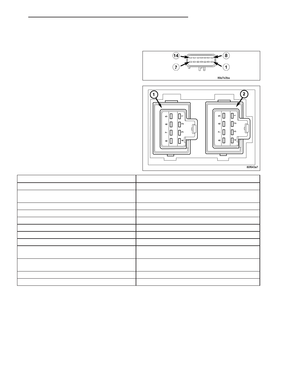
DIAGNOSIS AND TESTING - POWER WINDOW SWITCH

Remove the switch. Using an ohmmeter, test the win-
dow switch for continuity in all positions listed in the
Continuity Table. Refer to the Power Window Switch
Continuity table to determine if continuity is correct.

POWER WINDOW SWITCH CONTINUITY TABLE -
SEDAN

SWITCH POSITION

CONTINUITY BETWEEN

FRONT WINDOW SWITCH

LOCKOUT SWITCH (TOP

OF SWITCH DEPRESSED)

PIN 12 AND 5

LEFT FRONT UP

PIN 12 AND 14

RIGHT FRONT UP

PIN 12 AND 7

LEFT REAR UP

PIN 12 AND 8

LEFT REAR DOWN

PIN 12 AND 9

RIGHT REAR UP

PIN 12 AND 1

RIGHT REAR DOWN

PIN 12 AND 2

LEFT OR RIGHT REAR

SWITCH

OFF

PIN 2 AND 5
PIN 3 AND 8

UP

PIN 4 AND 5

DOWN

PIN 4 AND 8

To test the left front down and express down switch position, connect pin 4 to ground and pin 12 to a 12 volt source.
Using a voltmeter, measure for voltage from pin 13 to ground.

To test the right front down and express down switch position, connect pin 4 to ground and pin 12 to a 12 volt
source. Using a voltmeter, measure for voltage from pin 3 to ground. If the correct results are not obtained, replace
the switch.

PM

POWER WINDOWS

8N - 77

REMOVAL

1. Disconnect and isolate the battery negative cable.

2. Remove the front door bolster. (Refer to 23 -

BODY/DOOR - FRONT/DOOR - REMOVAL).

3. Disconnect the electrical harness connectors.

4. With the bolster on the bench, gently pry in on the

tabs of the mirror switch and push through the front
of the cover and remove.

INSTALLATION

1. Place the mirror switch in bolster opening and

firmly snap into place.

2. Connect the electrical harness connectors.

3. Install the front door bolster. (Refer to 23 - BODY/

DOOR - FRONT/DOOR - INSTALLATION)

4. Connect the battery negative cable.

8N - 78

POWER WINDOWS

PM

WINDOW MOTOR

REMOVAL

1. Move the window to the full UP position, if possible.

2. Disconnect and isolate the battery negative cable.

3. Remove door trim panel (Refer to 23 - BODY/DOOR - FRONT/TRIM PANEL - REMOVAL).

4. Disconnect electrical harness connector from motor.

5. Remove window regulator.

6. With regulator on bench, remove four screws retaining the motor to the regulator and remove motor.

INSTALLATION

1. With regulator on bench, install four screws retaining the motor to the regulator.

2. Install the window regulator.

3. Connect the electrical harness connector to window motor.

4. Install door trim panel (Refer to 23 - BODY/DOOR - FRONT/TRIM PANEL - INSTALLATION).

5. Connect battery negative cable.

PM

POWER WINDOWS

8N - 79

WINDOW REGULATOR MODULE

DESCRIPTION

The window regulator modules are directly connected
to each of the front door window regulator motors. The
window switches are hard wired by a mux circuit to
the respective window regulator module. The respec-
tive rear window motor is hard wired to the module.
The front window motor is directly attached to the
module. Both front door window switches have the
express down feature. The module will cease lowering
the front glass when a fully down position is sensed
through the hall effect sensor.

When a module must be replaced, it is necessary to
replace the entire regulator assembly.

OPERATION

When a door is opened, the respective module will receive a signal from the door ajar switch or the window drop
switch. The window drop switch is directly controlled by both the interior and the exterior door handle switches. The
drop switch is part of the door latch. This switch is faster than the door ajar switch to signal an open door operation.
At that point the module will drop the front door glass 10 mm (.5 in). However, if the window drop switch should fail,
the door ajar sense would also drop the window 10 mm (.5 in) and the module would set a trouble code. When the
module then receives a door ajar switch open (door closed) it would raise the window 10 mm (.5 in). The module
knows the position of the window by counting the motor rotation through the hall effect sensor in the module. If a
door window is raised while that door is open, the module will raise the glass up, but when the door is closed it will
raise the glass an additional 10 mm (.5 in). When the convertible top down switch is pressed to the first detent,
input is received by the driver window regulator module and passenger window regulator module, which will lower
the front windows approximately 40 mm (1.6 in), and lower the rear windows approximately 55 mm (2 in). After a
200 ms delay, it energizes the power top down relay to lower the convertible top.

DIAGNOSIS AND TESTING - WINDOW REGULATOR MODULE

Any diagnosis of the Window Regulator Modules should begin with the use of the scan tool. For informa-
tion on the use of the scan tool, refer to the appropriate Diagnostic Service Information.

For complete circuit diagrams, refer to the appropriate wiring information.

WARNING: Disable the airbag system before attempting any steering wheel, steering column, seat belt ten-
sioner, side airbag, or instrument panel component diagnosis or service. Disconnect and isolate the battery
negative (ground) cable, then wait two minutes for the airbag system capacitor to discharge before per-
forming further diagnosis or service. This is the only sure way to disable the airbag system. Failure to take
the proper precautions could result in accidental airbag deployment and possible personal injury.

8N - 80

POWER WINDOWS

PM


Content   ..  398  399  400  401   ..