Dodge Caliber. Manual - part 323


  Index      Dodge     Dodge Caliber - service repair manual 2007 year


Search            


Content   ..  321  322  323  324   ..


Dodge Caliber. Manual - part 323


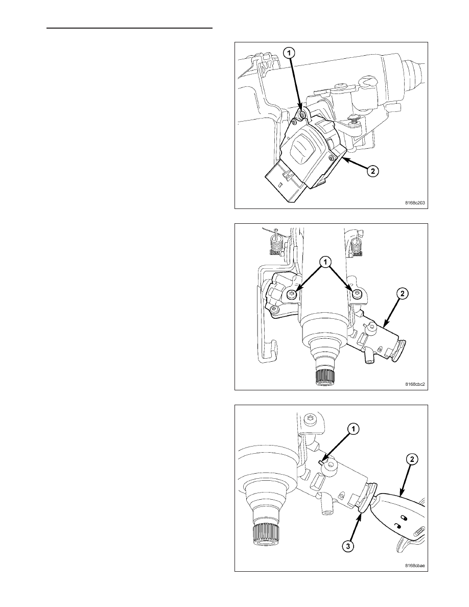
3. Install the ignition switch (2) mounting screw (1).

Tighten the screw to 2 N·m (18 in. lbs.).

NOTE: Ignition switch needs to be installed on
lock cylinder housing before housing installation
to clear tilt lever.

4. Position the lock cylinder housing in the RUN posi-

tion.

5. Align the lock cylinder housing (2) with the steering

column.

6. Install the two screws (1) fastening the lock cylin-

der housing (2) to the column. Tighten the screws
to 12 N·m (110 in. lbs.).

7. Place the actuator in the lock cylinder housing to

the RUN position (if not already there).

8. Insert the key into the key cylinder and turn the key

cylinder to the RUN position.

9. Align the retaining tab on the key cylinder with the

slot in the top of the lock cylinder housing.

10. Slide the key cylinder into the lock cylinder hous-

ing until the key cylinder retaining tab locks the
cylinder into place.

11. Rotate the key back and forth (OFF to START),

then remove and reinstall it, making sure the key
cylinder

and

lock

cylinder

housing

operate

properly.

PM

IGNITION CONTROL- SERVICE INFORMATION

8I - 53

12. Slide the ring of the SKREEM/WCM (2) over the

lock cylinder housing (3) and engage the retainer
fingers in the recesses formed on the lock cylin-
der housing.

13. Install the screw (1) fastening the SKREEM/WCM

(2) to the lock cylinder housing (3). Tighten the
screw to 2.5 N·m (22 in. lbs.).

14. Install

the

Steering

Column

Control

Module

(SCCM) (3) and all components removed to
access it. (Refer to 19 - STEERING/COLUMN/
STEERING

COLUMN

CONTROL MODULE

-

INSTALLATION)

15. Check operation of all steering column mounted

components.

8I - 54

IGNITION CONTROL- SERVICE INFORMATION

PM

KEY/LOCK CYLINDER

REMOVAL

The lock cylinder is inserted in the end of the housing opposite the ignition switch. The ignition key rotates the
cylinder to 5 different detentes:

Accessory

Off (lock)

Unlock

On/Run

Start

1. Disconnect negative cable from battery.

2. Place key cylinder in RUN position. Through the

hole in the lower shroud, depress lock cylinder
retaining tab and remove key cylinder.

INSTALLATION

1. Install key in lock cylinder. Turn key to RUN position (retaining tab on lock cylinder can be depressed).

2. The shaft at the end of the lock cylinder aligns with the socket in the end of the housing. To align the socket with

the lock cylinder, ensure the socket is in the Run position.

3. Align the lock cylinder with the grooves in the

housing. Slide the lock cylinder into the housing
until the tab sticks through the opening in the hous-
ing.

4. Turn the key to the Off position. Remove the key.

5. Connect negative cable to battery.

PM

IGNITION CONTROL- SERVICE INFORMATION

8I - 55

SENSOR-KNOCK

DESCRIPTION

The knock sensor is bolted to the cylinder block. The knock sensor is designed to detect engine vibration that is
caused by detonation or preignition.

OPERATION

When the knock sensor detects a knock in one of the cylinders, it sends an input signal to the PCM. In response,
the PCM retards ignition timing for all cylinders by a scheduled amount.

Knock sensors contain a piezoelectric material which constantly vibrates and sends an input voltage (signal) to the
PCM while the engine operates. As the intensity of the crystal’s vibration increases, the knock sensor output voltage
also increases.

The voltage signal produced by the knock sensor increases with the amplitude of vibration. The PCM receives as an
input the knock sensor voltage signal. If the signal rises above a predetermined level, the PCM will store that value
in memory and retard ignition timing to reduce engine knock. If the knock sensor voltage exceeds a preset value,
the PCM retards ignition timing for all cylinders. It is not a selective cylinder retard.

The PCM ignores knock sensor input during engine idle conditions. Once the engine speed exceeds a specified
value, knock retard is allowed.

Knock retard uses its own short term and long term memory program.

Long term memory stores previous detonation information in its battery-backed RAM. The maximum authority that
long term memory has over timing retard can be calibrated.

Short term memory is allowed to retard timing up to a preset amount under all operating conditions (as long as rpm
is above the minimum rpm) except WOT. The PCM, using short term memory, can respond quickly to retard timing
when engine knock is detected. Short term memory is lost any time the ignition key is turned off.

NOTE: Over or under tightening affects knock sensor performance, possibly causing improper spark con-
trol.

REMOVAL

The knock sensor bolts into the side of the cylinder
block in front of the starter under the intake manifold.

1. Disconnect the negative battery cable.

8I - 56

IGNITION CONTROL- SERVICE INFORMATION

PM


Content   ..  321  322  323  324   ..