Dodge Caliber. Manual - part 226


  Index      Dodge     Dodge Caliber - service repair manual 2007 year


Search            


Content   ..  224  225  226  227   ..


Dodge Caliber. Manual - part 226


7.

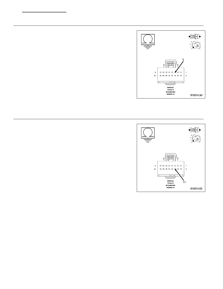
(D55) CAN B BUS (+) CIRCUIT FOR A SHORT TO GROUND

Turn the ignition off.

Disconnect the TIPM C3 harness connector.

Measure the resistance between ground and the (D55) CAN B Bus (+)
circuit.

Is the resistance above 1000.0 ohms?

Yes

>> Go To 8

No

>> Disconnect each CAN B Bus module one at a time while

observing the resistance to determine if the short is caused
by an internal short within a module. Replace the module, in
accordance with the service information, that when discon-
nected eliminates the short to ground. If the short condition
is still present with all CAN B Bus modules disconnected
use the Wiring Diagrams to help isolate and repair the
(D55) CAN B Bus (+) circuit for a short to ground.

Perform the BODY VERIFICATION TEST – VER 1. (Refer
to 8 - ELECTRICAL/ELECTRONIC CONTROL MODULES -
STANDARD PROCEDURE).

8.

(D54) CAN B BUS (-) CIRCUIT FOR A SHORT TO GROUND

Measure the resistance between ground and the (D54) CAN B Bus (-)
circuit.

Is the resistance above 1000.0 ohms?

Yes

>> Inspect the wiring and connectors for damage. If ok, replace

and program the Totally Integrated Power Module in accor-
dance with the service information. Perform the BODY
VERIFICATION TEST – VER 1. (Refer to 8 - ELECTRICAL/
ELECTRONIC CONTROL MODULES - STANDARD PRO-
CEDURE).

No

>> Disconnect each CAN B Bus module one at a time while

observing the resistance to determine if the short is caused
by an internal short within a module. Replace the module, in
accordance with the service information, that when discon-
nected eliminates the short to ground. If the short condition
is still present with all CAN B Bus modules disconnected
use the Wiring Diagrams to help isolate and repair the
(D54) CAN B Bus (-) circuit for a short to ground.

Perform the BODY VERIFICATION TEST – VER 1. (Refer to 8 - ELECTRICAL/ELECTRONIC CON-
TROL MODULES - STANDARD PROCEDURE).

PM

ELECTRONIC CONTROL MODULES - ELECTRICAL DIAGNOSTICS

8E - 15

9.

(D55) CAN B BUS (+) CIRCUIT SHORTED TO THE (D54) CAN B BUS (-) CIRCUIT

Turn the ignition off.

Disconnect the TIPM C3 harness connector.

Measure the resistance between the (D55) CAN B Bus (+) circuit and
(D54) CAN B Bus (-) circuit.

Is any resistance present?

Yes

>> Disconnect each CAN B Bus module one at a time while

observing the resistance to determine if the short is caused
by an internal short within a module. Replace the module, in
accordance with the service information, that when discon-
nected eliminates the short between the two circuits. If the
short condition is still present with all CAN B Bus modules
disconnected use the Wiring Diagrams to help isolate and
repair the (D55) CAN B Bus (+) circuit for a short to the
(D54) CAN B Bus (-) circuit.

Perform BODY VERIFICATION TEST – VER 1. (Refer to 8
-

ELECTRICAL/ELECTRONIC

CONTROL MODULES

-

STANDARD PROCEDURE).

No

>> Inspect the wiring and connectors for damage. If ok, replace and program the Totally Integrated Power

Module in accordance with the service information. Perform the BODY VERIFICATION TEST – VER 1.
(Refer to 8 - ELECTRICAL/ELECTRONIC CONTROL MODULES - STANDARD PROCEDURE).

8E - 16

ELECTRONIC CONTROL MODULES - ELECTRICAL DIAGNOSTICS

PM

U0021-CAN B BUS (+) CIRCUIT OPEN

For a complete wiring diagram Refer to Section 8W.

PM

ELECTRONIC CONTROL MODULES - ELECTRICAL DIAGNOSTICS

8E - 17

When Monitored:
With the ignition on and battery voltage between 10 and 16 volts.

Set Condition:
The TIPM detects the (D55) CAN B Bus (+) circuit is open.

Possible Causes

CAN B BUS TERMINAL PUSH OUT

SPREAD CAN B BUS TERMINAL

(D55) CAN B BUS (+) CIRCUIT OPEN

INTERNAL OPEN IN A CAN B BUS MODULE

Diagnostic Test

1.

TEST FOR INTERMITTENT CONDITION

Turn the ignition on.

With the scan tool, record and erase TIPM DTC’s.

Cycle the ignition from on to off 3 times.

Turn the ignition on.

With the scan tool, read active TIPM DTC’s.

Does the scan tool display this DTC as active?

Yes

>> Go To 2

No

>> The conditions that caused this code to set are not present at this time. Using the wiring diagram/sche-

matic as a guide, inspect the wiring and connectors.

2.

ATTEMPT TO ISOLATE THE OPEN CONDITION

Turn the ignition on.

With the scan tool select ECU View.

Verify that all CAN B Bus modules are communicating with the scan
tool.

NOTE: A red X will be next to a module that is not communicating,
indicating that the module is not active on the Bus network. A
green check indicates that the module is active on the Bus net-
work.

NOTE: If any module is not communicating, perform the appropri-
ate no response test procedure before proceeding.
Turn the ignition off.

Gain access to the Totally Integrated Power Module C3 harness con-
nector, but do not disconnect.

Using a fused jumper wire, connect one end to ground and with the
other end backprobe the CAN B Bus (-) circuit at the TIPM C3 harness
connector.

Turn the ignition on.

With the scan tool monitor the ECU View screen and document all modules that display a red X.

Are there any red X’s displayed next to any CAN B Bus modules?

Yes

>> Go To 3

No

>> Check backprobe connection to ground, make sure it is proper. The CAN B Bus open DTC may no

longer be active, it may be stored. Check all module connections.

Perform the BODY VERIFICATION TEST – VER 1. (Refer to 8 - ELECTRICAL/ELECTRONIC CON-
TROL MODULES - STANDARD PROCEDURE).

8E - 18

ELECTRONIC CONTROL MODULES - ELECTRICAL DIAGNOSTICS

PM


Content   ..  224  225  226  227   ..