Dodge Caliber. Manual - part 176
HEATER ENGINE BLOCK
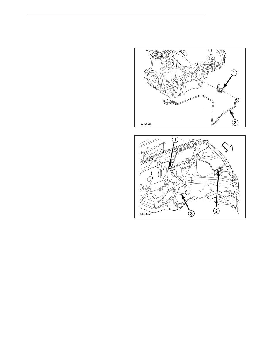
DESCRIPTION
The heater is mounted in a core hole (in place of a
core hole plug) in the engine block, with the heating
element immersed in coolant.
The engine block heater is available as an optional
accessory. The heater is powered by ordinary house
current (110 Volt AC) through a power cord and con-
nector.
OPERATION
The block heater element is submerged in the cooling system’s coolant. When electrical power (110 volt A.C.) is
applied to the element, it creates heat. This heat is transferred to the engine coolant. This provides easier engine
starting and faster warm-up when vehicle is operated in areas having extremely low temperatures.
DIAGNOSIS AND TESTING
ENGINE BLOCK HEATER TESTING
If unit does not operate, trouble can be in either the power cord or the heater element. Test power cord for conti-
nuity with a 110-volt voltmeter or 110-volt test light; test heater element continuity with an ohmmeter or 12-volt test
light.
PM
ENGINE
7 - 29