Dodge Caliber. Manual - part 1434


  Index      Dodge     Dodge Caliber - service repair manual 2007 year


Search            


Content   ..  1432  1433  1434  1435   ..


Dodge Caliber. Manual - part 1434


NOTE: It is only necessary to position the engine coolant reservoir and the power steering fluid reservoir
out of the way. Draining of the coolant and brake fluid is not required when servicing the washer bottle.

10. Remove the windshield washer reservoir (refer to 8 - ELECTRICAL/WIPERS/WASHERS/WASHER RESER-

VOIR - REMOVAL).

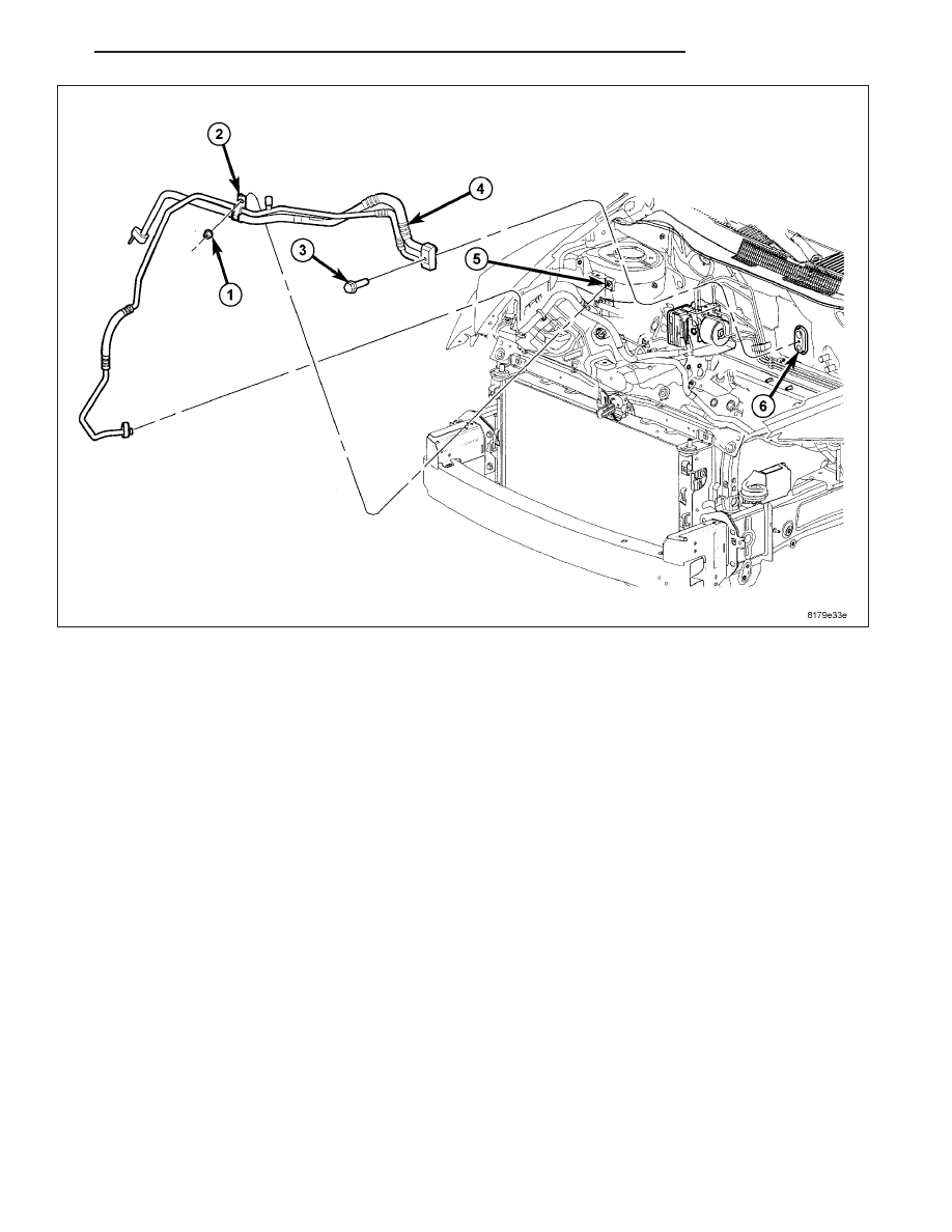
11. Remove the nut (1) that secures the refrigerant line retaining bracket (2) to the right front strut tower (5).

12. On RHD models, disengage the retainers that secure the power brake booster vacuum supply hose to the dash

panel and position the vacuum line out of the way.

13. Remove the bolt (3) that secures the A/C liquid and suction line assembly (4) to the A/C evaporator (6).

14. Disconnect the A/C liquid and suction line assembly from the A/C evaporator and remove and discard the dual-

plane seals.

15. Install plugs in, or tape over the opened refrigerant line fittings and the evaporator ports.

16. Remove the A/C liquid and suction line assembly from the engine compartment.

PM

PLUMBING

24 - 153

Lower A/C Suction Line

1. Disconnect and isolate the negative battery cable.

2. Recover the refrigerant from the refrigerant system

(refer to 24 - HEATING & AIR CONDITIONING/
PLUMBING

-

STANDARD

PROCEDURE

-

REFRIGERANT SYSTEM RECOVERY).

3. Raise and support the vehicle.

4. Remove the right front wheel (refer to 22 - TIRES/

WHEELS - REMOVAL).

5. Remove the three push-pin retainers (1) and three

screws (2) that secure the front portion of the right
front wheelhouse splash shield (3) to body (4) and
position the front of the wheelhouse splash shield
out of the way to gain access to the A/C accumu-
lator (refer to 23 - BODY/EXTERIOR/SPLASH
SHIELD-FRONT WHEELHOUSE - REMOVAL).

6. Remove the nut (2) that secures the lower A/C suc-

tion line (3) to the A/C accumulator (1).

7. Disconnect the lower A/C suction line from the A/C

accumulator and remove and discard the O-ring
seal and gasket.

8. Install plugs in, or tape over the opened suction

line fitting and the accumulator port.

9. Remove the nut (1) that secures the lower A/C suc-

tion line (2) to the A/C compressor (3).

10. Disconnect the lower A/C suction line from the

A/C compressor and remove and discard the
O-ring seal and gasket.

11. Install plugs in, or tape over the opened suction

line fitting and the compressor port.

12. Remove the lower A/C suction line from the

engine compartment.

24 - 154

PLUMBING

PM

INSTALLATION

NOTE: Replacement of the refrigerant line O-ring seals and gaskets is required anytime a refrigerant line is
opened. Failure to replace the rubber O-ring seals and metal gaskets could result in a refrigerant system
leak.

NOTE: LHD model shown in illustrations. RHD model similar.

Upper A/C Suction Line

1. Position the A/C liquid and suction line assembly (4) into the engine compartment.

2. Remove the tape or plugs from the refrigerant line fittings and the evaporator ports.

3. Lubricate the rubber O-rings on new dual-plan seals with clean refrigerant oil and install the seals onto the liquid

and suction line fittings. Use only the specified seals as they are made of special materials compatible to the
R-134a system. Use only refrigerant oil of the type recommended for the A/C compressor in the vehicle.

4. Connect the A/C liquid and suction line assembly to the A/C evaporator (6).

5. Install the bolt (3) that secures the A/C liquid and suction line assembly to the A/C evaporator. Tighten the bolt

to 12 N·m (105 in. lbs.).

6. On RHD models, engage the retainers that secure the power brake booster vacuum supply hose to the dash

panel.

7. Install the nut (1) that secures the refrigerant line bracket (2) to the right front strut tower (5). Tighten the nut to

4.5 N·m (40 in. lbs.).

8. Install the windshield washer reservoir, power steering reservoir and the engine coolant reservoir (refer to 8 -

ELECTRICAL/WIPERS/WASHERS/WASHER RESERVOIR - INSTALLATION).

PM

PLUMBING

24 - 155

9. Position the heat shield (3) onto the studs (2)

located on the dash panel in the engine compart-
ment.

10. Install the three nuts (1) that secure the heat

shield to the dash panel. Tighten the nuts to 1
N·m (10 in. lbs.).

NOTE:

Illustration

shown

with

front

fascia

removed for clarity.

11. Raise and support the vehicle.

12. Remove the tape or plugs from the liquid line fit-

ting and the condenser port.

13. Lubricate a new rubber O-ring seal with clean

refrigerant oil and install it and a new gasket onto
the liquid line fitting. Use only the specified O-ring
as it is made of a special material for the R-134a
system. Use only refrigerant oil of the type recom-
mended for the A/C compressor in the vehicle.

14. Reach up through the opening in the bottom of

the front fascia and connect the A/C liquid line (1)
to the A/C condenser (2) and install the retaining
nut (3). Tighten the nut to 5 N·m (44 in. lbs.).

15. Install the A/C accumulator (refer to 24 - HEAT-

ING & AIR CONDITIONING/PLUMBING/ACCU-
MULATOR - INSTALLATION).

16. Lower the vehicle.

17. Reconnect the negative battery cable.

18. Evacuate the refrigerant system (refer to 24 - HEATING & AIR CONDITIONING/PLUMBING - STANDARD

PROCEDURE - REFRIGERANT SYSTEM EVACUATE)

19. Charge the A/C system (refer to 24 - HEATING & AIR CONDITIONING/PLUMBING - STANDARD PROCE-

DURE - REFRIGERANT SYSTEM CHARGE).

24 - 156

PLUMBING

PM


Content   ..  1432  1433  1434  1435   ..