Dodge Caliber. Manual - part 1414


  Index      Dodge     Dodge Caliber - service repair manual 2007 year


Search            


Content   ..  1412  1413  1414  1415   ..


Dodge Caliber. Manual - part 1414


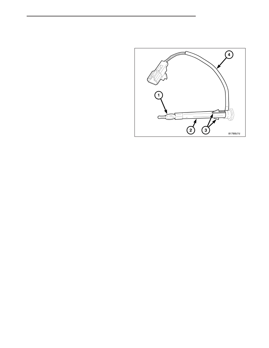
SENSOR-EVAPORATOR TEMPERATURE

DESCRIPTION

The evaporator temperature sensor measures the
temperature of the conditioned air downstream of the
A/C evaporator. The evaporator temperature sensor is
an electrical thermistor (1) mounted on the end of a
molded plastic housing (2) that is inserted into the
driver side of the HVAC housing near the coldest point
of the A/C evaporator. The evaporator temperature
sensor is retained in the HVAC housing by two integral
retaining tabs (3) and is connected to the vehicle elec-
trical system by use of a wire lead and connector (4)
with two terminals.

OPERATION

The evaporator temperature sensor monitors the surface temperature of A/C evaporator and supplies an input signal
to the A/C-heater control. The A/C-heater control uses the evaporator temperature sensor input signal to optimize
A/C system performance and to protect the A/C system from evaporator freezing. The evaporator temperature sen-
sor will change its internal resistance in response to the temperatures it monitors and is connected to the A/C-heater
control through sensor ground circuit and a 5-volt reference signal circuit. As the temperature of the A/C evaporator
decreases, the internal resistance of the evaporator temperature sensor decreases.

The A/C-heater control uses the monitored voltage reading as an indication of evaporator temperature. The A/C-
heater control is programmed to respond to this input by requesting the powertrain control module (PCM) or the
engine control module (ECM) (depending on engine application) to adjust the compressor swash plate angle as
necessary to optimize A/C system performance and to protect the A/C system from evaporator freezing (refer to 24
- HEATING & AIR CONDITIONING/PLUMBING/COMPRESSOR-A/C - OPERATION for more information).

The evaporator temperature sensor is diagnosed using a scan tool (refer to 24 - HEATING & AIR CONDITIONING
- DIAGNOSIS AND TESTING and to 24 - HVAC Electrical Diagnostics for more information).

The evaporator temperature sensor cannot be adjusted or repaired and, if faulty or damaged, it must be replaced.

REMOVAL

NOTE: LHD model shown. RHD model similar.

PM

CONTROLS

24 - 73

1. Remove the HVAC housing assembly and place it

on a workbench (refer to 24 - HEATING & AIR
CONDITIONING/DISTRIBUTION /HOUSING-HVAC
- HOUSING-HVAC ASSEMBLY - REMOVAL).

2. Remove the air distribution housing from the HVAC

housing (refer to 24 - HEATING & AIR CONDI-
TIONING/DISTRIBUTION/HOUSING-HVAC

-

HOUSING-AIR DISTRIBUTION - REMOVAL).

3. Using needle nose pliers (1) , disengage the two

retaining tabs (2) that secure the evaporator tem-
perature sensor (3) to the driver side of the HVAC
housing (4) and remove the sensor.

INSTALLATION

NOTE: LHD model shown. RHD model similar.

1. Install the evaporator temperature sensor (1) into

the driver side of the HVAC housing (2). Make sure
the retaining tabs (3) are fully engaged to the hous-
ing.

2. Install the air distribution housing onto the HVAC

housing (refer to 24 - HEATING & AIR CONDI-
TIONING/DISTRIBUTION/HOUSING-HVAC

-

HOUSING-AIR DISTRIBUTION - INSTALLATION).

3. Install the HVAC housing assembly (refer to 24 -

HEATING & AIR CONDITIONING/DISTRIBUTION/
HOUSING-HVAC - HOUSING-HVAC ASSEMBLY -
INSTALLATION).

24 - 74

CONTROLS

PM

TRANSDUCER-A/C PRESSURE

DESCRIPTION

The A/C pressure transducer (1) is a switch that is
installed on a fitting located on the A/C discharge line.
An internally threaded fitting on the A/C pressure
transducer connects it to the externally threaded
Schrader-type fitting on the A/C discharge line. A rub-
ber O-ring seals the connection between the A/C pres-
sure transducer and the discharge line fitting. The A/C
pressure transducer is connected to the vehicle elec-
trical system by a molded plastic connector with three
terminals.

OPERATION

The A/C pressure transducer monitors the pressures in the high side of the refrigerant system through its connection
to a fitting on the A/C discharge line and its internal resistance changes in response to the pressures it monitors.
The powertrain control module (PCM) or the engine control module (ECM) (depending on engine application) pro-
vides a five volt reference signal and a sensor ground to the A/C pressure transducer, then monitors the output
voltage of the transducer on a sensor return circuit to determine refrigerant pressure. The PCM/ECM is programmed
to respond to this and other sensor inputs by controlling the operation of the swashplate within the A/C compressor
and the radiator cooling fan to help optimize A/C system performance and to protect the system components from
damage. The PCM adjusts the swashplate to nearly a zero degree angle (low compressor displacement) when high
side pressure rises above 3130 kPa (454 psi) and re-adjusts the swashplate to a greater angle (higher compressor
displacement) when high side pressure drops below 1999 kPa (290 psi). The A/C pressure transducer also reduces
the swashplate angle if the high side pressure drops below 200 kPa (29 psi) and will increase the swashplate angle
when the high side pressure rises above 234 -262 kPa (34 - 38 psi). When the refrigerant pressure rises above
1655 kPa (240 psi), the PCM will actuate the cooling fan.

A Schrader-type valve in the A/C discharge line fitting permits the A/C pressure transducer to be removed or
installed without disturbing the refrigerant in the A/C system.

The A/C pressure transducer is diagnosed using a scan tool. Refer to 9 - Engine Electrical Diagnostics for more
information.

The A/C pressure transducer cannot be adjusted or repaired and, if faulty or damaged it must be replaced.

REMOVAL

NOTE: It is not necessary to discharge the refrigerant system to replace the A/C pressure transducer.

PM

CONTROLS

24 - 75

NOTE: Typical A/C pressure transducer shown.

1. Disconnect and isolate the negative battery cable.

2. Remove the upper radiator closure panel and care-

fully pull the top of the fascia forward to gain
access to the A/C pressure transducer (2) (refer to
23 - BODY/EXTERIOR/CLOSURE PANEL-UPPER
RADIATOR - REMOVAL).

3. Reach down through the opening between the A/C

condenser and the front fascia and disconnect the
wire harness connector (1) from the A/C pressure
transducer located on the A/C discharge line (3).

4. Remove the A/C pressure transducer from the fit-

ting on the A/C discharge line and remove and dis-
card the O-ring seal.

INSTALLATION

NOTE: Use only the specified O-ring as it is made of special material for R-134a. Use only refrigerant oil of
the type required for the A/C compressor.

NOTE: Typical A/C pressure transducer shown.

1. Lubricate a new rubber O-ring seal (4) with clean

refrigerant oil and install it onto the discharge line
fitting (3).

2. Install the A/C pressure transducer (2) onto the A/C

discharge line. Tighten the A/C pressure transducer
securely.

3. Connect the wire harness connector (1) to the A/C

pressure transducer.

4. Install the upper radiator closure panel (refer to 23

-

BODY/EXTERIOR/CLOSURE

PANEL-UPPER

RADIATOR - INSTALLATION).

5. Reconnect the negative battery cable.

24 - 76

CONTROLS

PM


Content   ..  1412  1413  1414  1415   ..