Content .. 1235 1236 1237 1238 ..
Dodge Caliber. Manual - part 1237
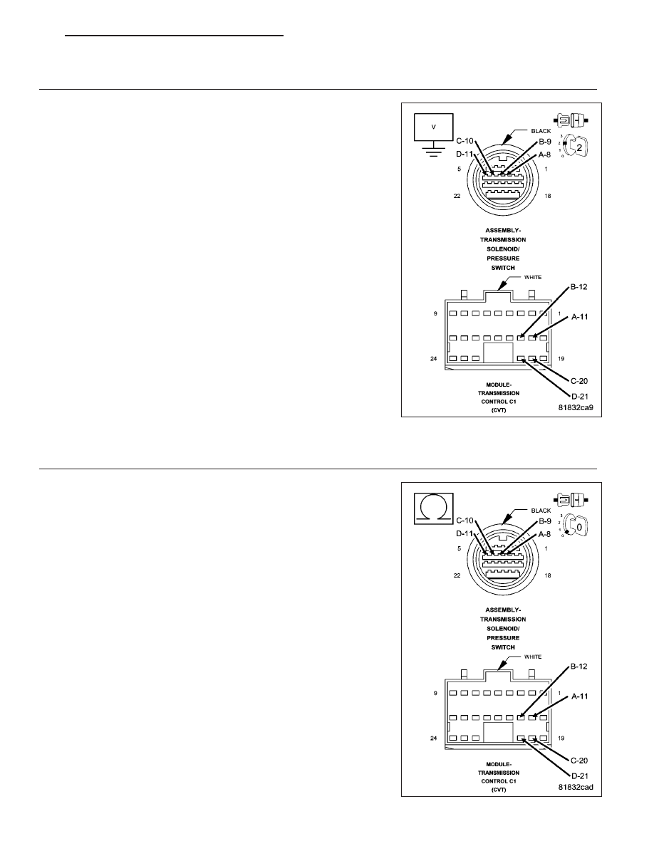
2.
CHECK THE (T314) A, (T315) B, (T316) C, AND (T317) D STEP MOTOR CONTROL CIRCUIT(S) FOR A
SHORT TO VOLTAGE
Turn the ignition off to the lock position.
Disconnect the TCM C1 and C2 harness connectors.
Disconnect the Transmission Solenoid/Pressure Switch Assembly har-
ness connector.
Ignition on, engine not running.
Measure separately the voltage of the (T314) A, (T315) B, (T316) C,
and (T317) D Step Motor Control circuits.
Is the voltage above .05 volts for any of the Step Motor Control
circuits?
Yes
>> Repair the (T314) A, (T315) B, (T316) C, and/or (T317) D
Step Motor Control circuit(s) for a short to voltage.
Perform CVT VERIFICATION TEST. (Refer to 21 - TRANS-
MISSION/TRANSAXLE/AUTOMATIC - CVT - STANDARD
PROCEDURE)
No
>> Go To 3
3.
CHECK THE (T314) A, (T315) B, (T316) C, AND (T317) D STEP MOTOR CONTROL CIRCUIT(S) FOR AN
OPEN
Turn the ignition off to the lock position.
Measure separately the resistance of the (T314) A, (T315) B, (T316) C,
and (T317) D Step Motor Control circuits between the TCM C1 harness
connector and the Transmission Solenoid/Pressure Switch harness con-
nector.
Is the resistance above 5.0 ohms for any of the Step Motor
Control circuits?
Yes
>> Repair the (T314) A, (T315) B, (T316) C, and/or (T317) D
Step Motor Control circuit(s) for an open.
Perform CVT VERIFICATION TEST. (Refer to 21 - TRANS-
MISSION/TRANSAXLE/AUTOMATIC - CVT - STANDARD
PROCEDURE)
No
>> Go To 4
PM
AUTOMATIC - CVT-ELECTRICAL DIAGNOSTICS
21 - 247