Dodge Caliber. Manual - part 1169


  Index      Dodge     Dodge Caliber - service repair manual 2007 year


Search            


Content   ..  1167  1168  1169  1170   ..


Dodge Caliber. Manual - part 1169


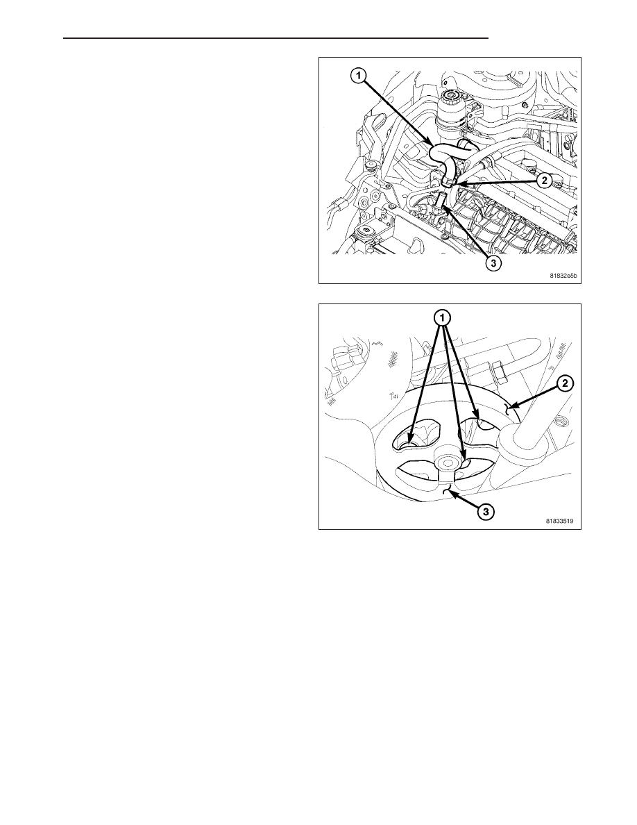
5. Remove the hose clamp (2) securing the supply

hose (1) at the pump.

6. Remove the supply hose (1) from the pump (3).

7. Remove the drive belt (2). (Refer to 7 - COOLING/

ACCESSORY DRIVE/DRIVE BELTS - REMOVAL)

8. Remove the three pump mounting bolts (1) through

the pulley (3) openings.

9. Remove the power steering pump.

DIESEL ENGINE

NOTE: Before proceeding, (Refer to 19 - STEERING - WARNING).

1. Siphon as much fluid as possible from the power steering fluid reservoir.

2. Remove the engine appearance cover.

PM

PUMP

19 - 63

3. Remove the pressure hose routing bracket bolt (2)

to the upper mount (7).

4. Remove the pressure hose (3) at the pump pres-

sure port (4).

5. Remove the hose clamp (3) securing the supply

hose (1) at the pump.

6. Remove the supply hose (1) from the pump (2).

7. Remove the drive belt. (Refer to 7 - COOLING/AC-

CESSORY DRIVE/DRIVE BELTS - REMOVAL)

8. Remove the two pump mounting bolts (1) through

the pulley (2) openings.

19 - 64

PUMP

PM

9. Remove the rear pump mounting bolt (2) behind

the pump (1).

10. Remove the power steering pump (1).

INSTALLATION

GAS ENGINE

1. Using a lint free towel, wipe clean the open power

steering pressure hose end and the power steering
pump port. Replace any used O-rings with new.
Lubricate the O-ring with clean power steering fluid.

2. Place the pump in mounting position. Install the

three bolts (1) through the pulley (3) openings.
Tighten the mounting bolts (1) to 20 N·m (177 in.
lbs.).

3. Install the drive belt (2). (Refer to 7 - COOLING/

ACCESSORY

DRIVE/DRIVE

BELTS

-

INSTALLATION)

PM

PUMP

19 - 65

4. Install the supply hose (1) at the pump (3).

5. Clamp the hose clamp (2) securing the supply

hose (1) to the pump.

6. Install the pressure hose (3) at the pump pressure

port (5). Tighten the tube nut to 32 N·m (24 ft. lbs.).

7. Install the pressure hose routing bracket bolt (2) to

the upper mount (8).

8. Fill and bleed the power steering system. (Refer to

19 - STEERING - STANDARD PROCEDURE)

9. Check for leaks.

10. Install the engine appearance cover.

19 - 66

PUMP

PM


Content   ..  1167  1168  1169  1170   ..