Dodge Caliber. Manual - part 82


  Index      Dodge     Dodge Caliber - service repair manual 2007 year


Search            


Content   ..  80  81  82  83   ..


Dodge Caliber. Manual - part 82


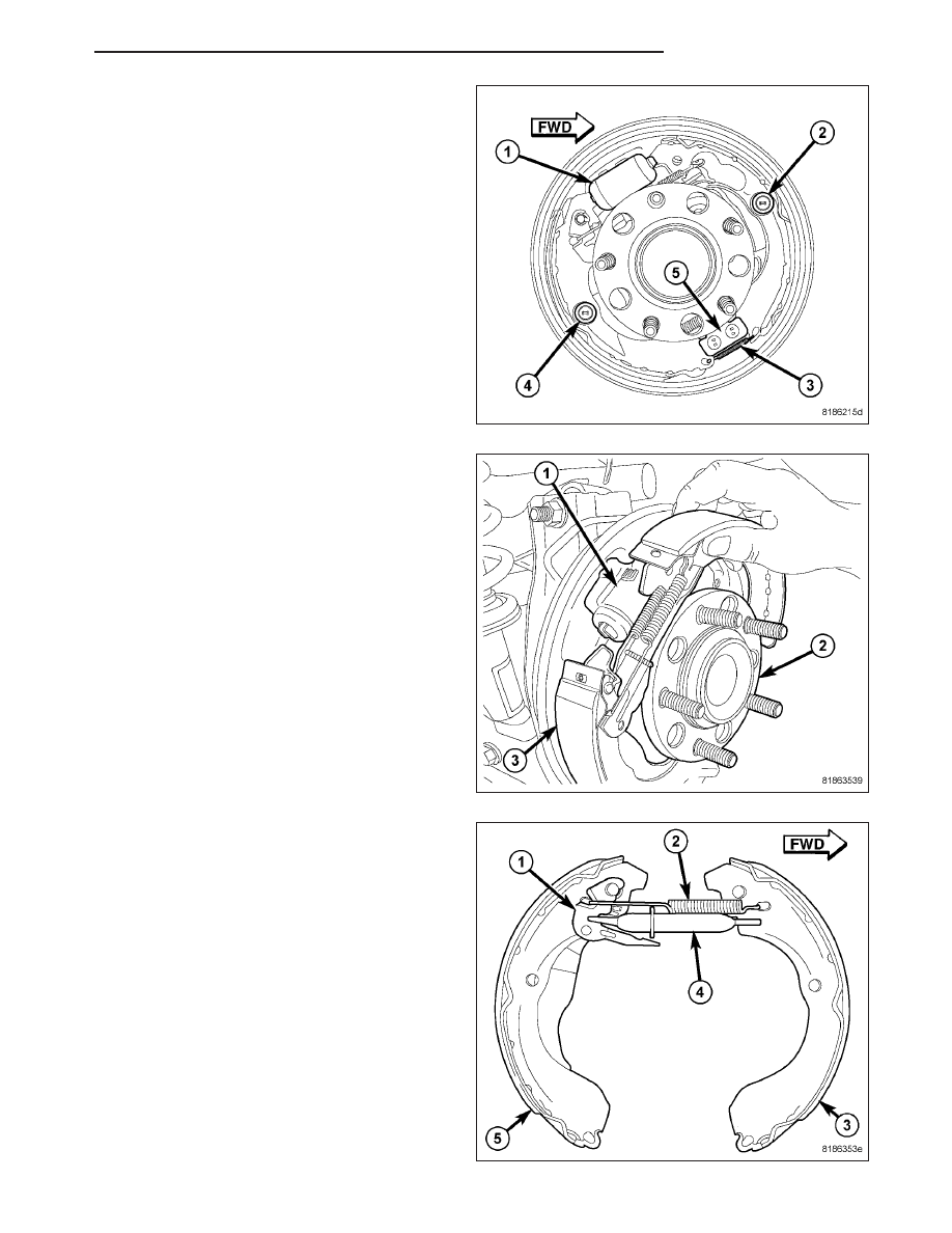
8. Compress and remove the hold-down spring (2)

retaining the front shoe to the support plate.

9. Remove both brake shoes from the wheel cylinder.

10. Remove both shoes and remaining parts as an

assembly (3) through the opening between the
wheel cylinder (1) and support plate hub and
bearing.

11. Place the shoe assembly outboard-side-up on a

flat surface.

12. Remove the adjuster spring (2) from the leading

shoe (3) and the lever pawl (1).

13. Remove the lever pawl (1) from the pivot on the

rear shoe (5).

PM

BRAKES - BASE

5 - 29

14. Flip the shoe assembly over to show the inboard

side.

15. Remove the upper shoe return spring (1).

16. Remove the adjuster (5) from the shoes and park-

ing brake lever (2).

CLEANING

WARNING: Dust and dirt accumulating on brake parts during normal use may contain asbestos fibers from
production or aftermarket brake linings. Breathing excessive concentrations of asbestos fibers can cause
serious bodily harm. Exercise care when servicing brake parts. Do not sand or grind brake lining unless
equipment used is designed to contain the dust residue. Do not clean brake parts with compressed air or
by dry brushing. Cleaning should be done by dampening the brake components with a fine mist of water,
then wiping the brake components clean with a dampened cloth. Dispose of cloth and all residue containing
asbestos fibers in an impermeable container with the appropriate label. Follow practices prescribed by the
Occupational Safety And Health Administration (OSHA) and the Environmental Protection Agency (EPA) for
the handling, processing, and disposing of dust or debris that may contain asbestos fibers.

INSPECTION

Inspect the shoe linings. Rear brake shoe linings should show contact across the entire width of the lining and also
from the heel to the toe of the lining. Replace the shoes if noted otherwise. Brake shoes with lack of contact at the
toe or heel of the brake shoe lining may be improperly ground.

Clean and inspect the brake support plate and shoe adjuster screw. Apply a thin coat of Mopar

T

Multi-Purpose

Grease or equivalent to the threads of the self-adjuster. Replace the adjuster screw if it is corroded.

NOTE: Adjuster screws are different side-to-side. Left side adjuster screws have left-hand threads and right
side adjuster screws have right-hand threads.

Inspect the return springs and hold-down spring clips. If the existing brake shoe return springs or hold-down spring
clips have been overheated or damaged, replace them. Overheating indications are paint discoloration or distorted
end coils.

INSTALLATION

NOTE: Perform Step 1 through Step 21 on each side of vehicle to complete shoe set installation, then pro-
ceed to Step 22.

5 - 30

BRAKES - BASE

PM

1. Lubricate shoe contact areas on support plate and

anchor using Mopar

T

Brake Lubricant or equiva-

lent.

2. Lubricate the adjuster screw threads with Mopar

T

Brake Lubricant or equivalent. Turn adjuster wheel
in until it is completely seated.

NOTE: Right side drum brake shown. Left side is
typical.

3. Place one front shoe (6) and one rear shoe (3)

inboard-side-up on a flat surface. (rear shoe has
parking brake lever attached to it).

4. Install the adjuster (5), adjuster wheel toward the

rear, between the two brake shoes. Make sure the
wide notch in the rear fork aligns with the parking
brake lever (2).

5. Install the upper return spring (1) as shown.

6. Flip the shoe assembly over to show the outboard

side.

7. Install the lever pawl (1) onto the pivot located on

the rear shoe (5).

8. Install the adjuster spring (2) between the front

shoe (3) and the lever pawl (1).

PM

BRAKES - BASE

5 - 31

9. Install the pre-assembled brake shoe assembly (3)

through the opening between the wheel cylinder (1)
and support plate hub and bearing.

10. Insert the upper tips of the brake shoes into the

grooves of the wheel cylinder (1) pistons.

11. Position the bottom of the front shoe against the

anchor pin (5).

12. Install a shoe hold-down pin from the rear,

through the support plate and the front shoe.

13. Compress and install the hold-down spring (2)

retaining the front shoe to the support plate.

14. Compress the parking brake cable return spring,

then carefully install the cable onto the parking
brake lever. Release the spring guiding it beneath
the retaining tab on the lever.

5 - 32

BRAKES - BASE

PM


Content   ..  80  81  82  83   ..