Dodge Durango (HB). Manual - part 952
P2074-MAP/TPS CORRELLATION - HIGH AIRFLOW/VACUUM LEAK DETECTED (CONTINUED)
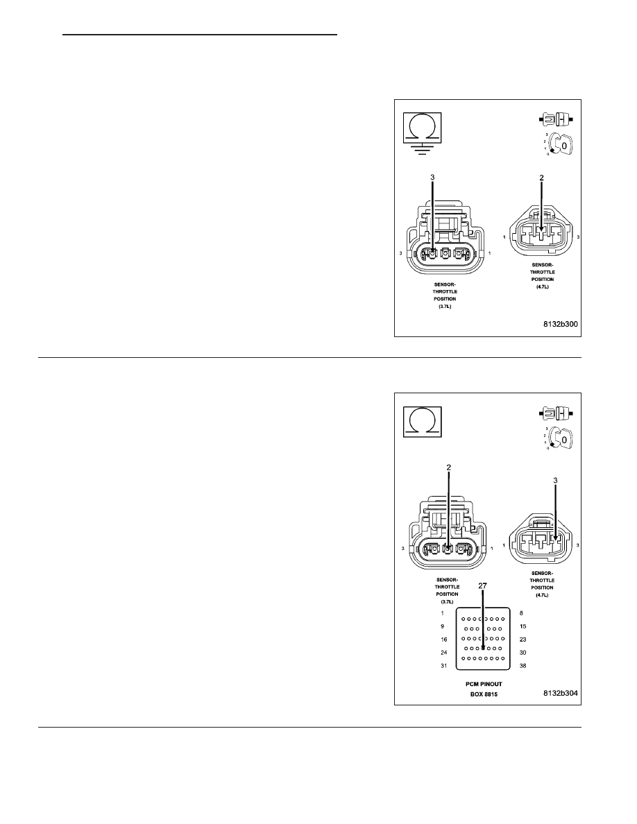
9.
(K22) TP SENSOR NO.1 SIGNAL CIRCUIT SHORTED TO GROUND
Measure the resistance between ground and the (K22) TP Sensor
No.1 Signal circuit in the TP Sensor harness connector.
Is the resistance below 100 ohms?
Yes
>> Repair the short to ground in the (K22) TP Sensor No.1
Signal circuit.
Perform the POWERTRAIN VERIFICATION TEST. (Refer
to 9 - ENGINE - STANDARD PROCEDURE)
No
>>
Go To 10
10.
EXCESSIVE RESISTANCE IN THE (K900) SENSOR GROUND CIRCUIT
CAUTION: Do not probe the PCM harness connectors. Probing
the PCM harness connectors will damage the PCM terminals
resulting in poor terminal to pin connection. Install Miller Special
Tool #8815 to perform diagnosis.
Measure the resistance of the (K900) Sensor ground circuit from the
TP Sensor harness connector to the appropriate terminal of special
tool #8815.
Is the resistance below 5.0 ohms?
Yes
>> Go To 17
No
>> Repair the excessive resistance in the (K900) Sensor
ground circuit.
Perform the POWERTRAIN VERIFICATION TEST. (Refer
to 9 - ENGINE - STANDARD PROCEDURE)
HB
ENGINE ELECTRICAL DIAGNOSTICS
9 - 807