Dodge Durango (HB). Manual - part 915
P0591-SPEED CONTROL SWITCH 2 PERFORMANCE (CONTINUED)
4.
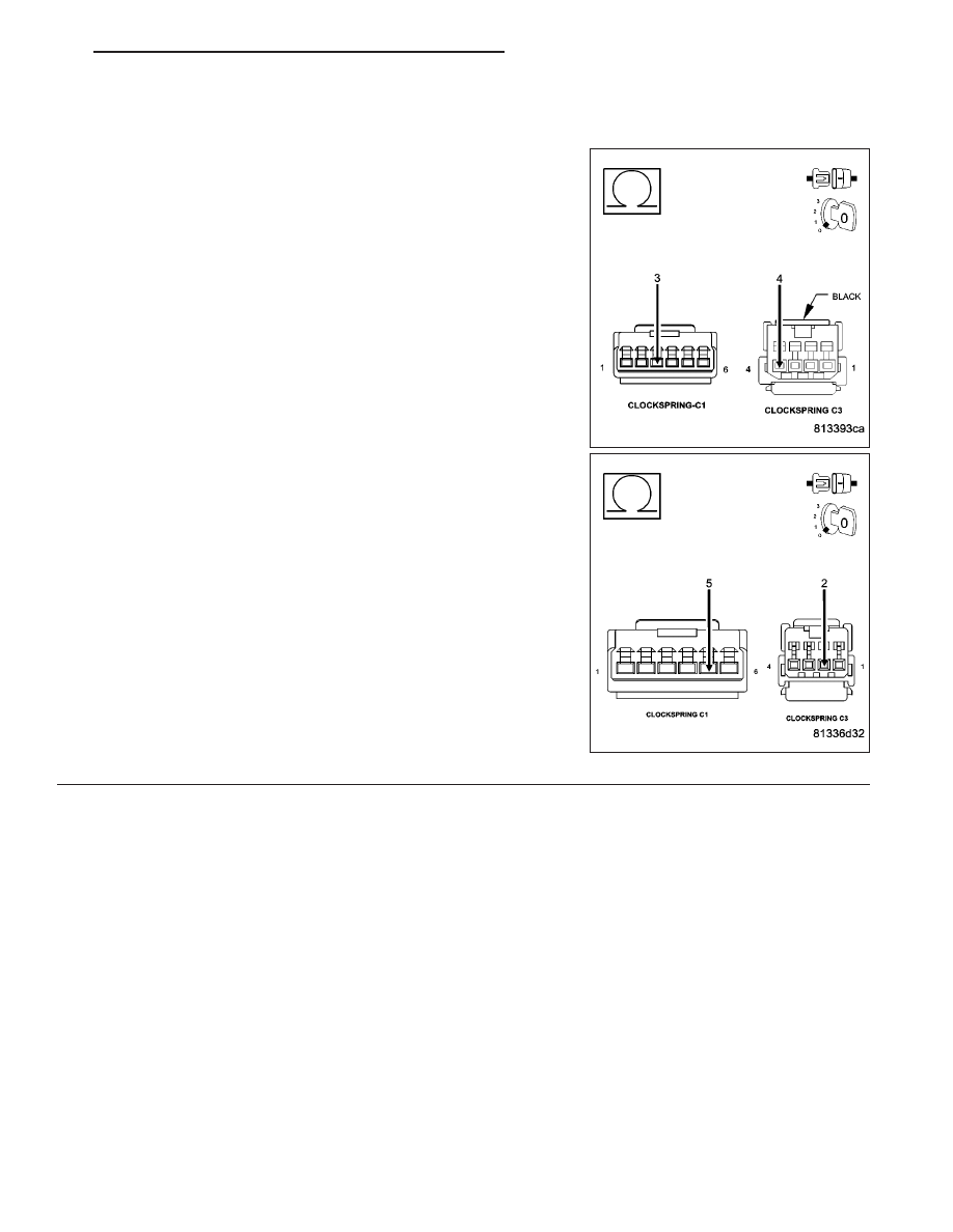
CLOCKSPRING
Turn the ignition off.
Disconnect the C1 and C3 Clockspring harness connectors per Ser-
vice Information.
Measure the resistance of the (V38) S/C Switch No.2 Signal circuit
between the C1 and C3 Clockspring harness connectors.
Measure the resistance of the (V937) Switch Return circuit between
the C1 and C3 Clockspring harness connectors.
Is the resistance above 5.0 ohms?
Yes
>> Replace the Clockspring per Service Information.
Perform the POWERTRAIN VERIFICATION TEST. (Refer
to 9 - ENGINE - STANDARD PROCEDURE)
No
>> Go To 5
NOTE: Connect the Clockspring harness connectors per Service
Information before continuing.
HB
ENGINE ELECTRICAL DIAGNOSTICS
9 - 659