Dodge Durango (HB). Manual - part 910


  Index      Dodge     Dodge Durango (HB) - service repair manual 2005 year


Search            


Content   ..  908  909  910  911   ..


Dodge Durango (HB). Manual - part 910


P0586-SPEED CONTROL VACUUM CONTROL CIRCUIT (CONTINUED)
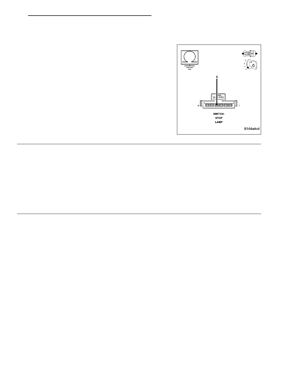
9.

(V32) S/C SUPPLY CIRCUIT SHORTED TO GROUND

Measure the resistance between ground and the (V32) S/C Supply cir-
cuit at the Speed Control Servo harness connector.

Is the resistance below 100 ohms?

Yes

>> Repair the short to ground in the (V32) S/C Supply circuit.

Perform the POWERTRAIN VERIFICATION TEST. (Refer
to 9 - ENGINE - STANDARD PROCEDURE)

No

>> Go To 10

10.

PCM

NOTE: Before continuing, check the PCM harness connector terminals for corrosion, damage, or terminal
push out. Repair as necessary.

Were there any problems found?

Yes

>> Repair as necessary.

Perform the POWERTRAIN VERIFICATION TEST. (Refer to 9 - ENGINE - STANDARD PROCEDURE)

No

>> Replace and program the Powertrain Control Module per Service Information.

Perform the POWERTRAIN VERIFICATION TEST. (Refer to 9 - ENGINE - STANDARD PROCEDURE)

HB

ENGINE ELECTRICAL DIAGNOSTICS

9 - 639

P0585-SPEED CONTROL SWITCH 1/2 CORRELATION (5.7L)

9 - 640

ENGINE ELECTRICAL DIAGNOSTICS

HB

P0585-SPEED CONTROL SWITCH 1/2 CORRELATION (5.7L) (CONTINUED)

For the Engine circuit diagram (Refer to 9 - ENGINE - SCHEMATICS AND DIAGRAMS).

For a complete wiring diagram Refer to Section 8W.

When Monitored:
Ignition on.

Set Condition:
Cruise Switch inputs are not coherent with each other. Example: PCM is reading Switch No.1 as Accel and
Switch No.2 as Coast at the same time. One trip fault.

Possible Causes

S/C SWITCH SIGNAL CIRCUITS SHORTED TO BATTERY VOLTAGE

RESISTANCE IN THE S/C SWITCH SIGNAL CIRCUITS

RESISTANCE IN THE (V937) SWITCH RETURN CIRCUIT

S/C SWITCH SIGNAL CIRCUITS SHORTED TO THE (V937) SWITCH RETURN CIRCUIT

(V37) S/C SWITCH NO.1 SIGNAL CIRCUIT SHORTED TO THE (V38) S/C SWITCH NO.2 SIGNAL CIRCUIT

S/C SWITCH SIGNAL CIRCUITS SHORTED TO GROUND

CLOCKSPRING

SPEED CONTROL ON/OFF SWITCH

SPEED CONTROL RESUME/ACCEL SWITCH

PCM

Always perform the Pre-Diagnostic Troubleshooting procedure before proceeding. (Refer to 9 - ENGINE -
DIAGNOSIS AND TESTING).

Diagnostic Test

1.

ACTIVE DTC

Ignition on, engine not running.

NOTE: This DTC may be the result of pressing two Speed Control Switch buttons simultaneously for more
than 450 msec.
Ask the customer if it is possible that two buttons were pressed at the same time before this DTC set. If this is the
case, no repair is necessary.

Is the DTC active a this time?

Yes

>> Go To 2

No

>> Refer to the INTERMITTENT CONDITION Diagnostic Procedure.

Perform the POWERTRAIN VERIFICATION TEST. (Refer to 9 - ENGINE - STANDARD PROCEDURE)

2.

SPEED CONTROL ON/OFF SWITCH

With the scan tool, monitor the Speed Control Switch voltage.

Disconnect the Speed Control On/Off Switch harness connector.

Did the voltage change to above 4.8 volts?

Yes

>> Replace the Speed Control On/Off Switch.

Perform the POWERTRAIN VERIFICATION TEST. (Refer to 9 - ENGINE - STANDARD PROCEDURE)

No

>> Go To 3

HB

ENGINE ELECTRICAL DIAGNOSTICS

9 - 641

P0585-SPEED CONTROL SWITCH 1/2 CORRELATION (5.7L) (CONTINUED)

3.

SPEED CONTROL RESUME/ACCEL SWITCH

With the scan tool, monitor the Speed Control Switch voltage.

Disconnect the Speed Control Resume/Accel Switch harness connector.

Did the voltage change to above 4.8 volts?

Yes

>> Replace the Speed Control Resume/Accel Switch.

Perform the POWERTRAIN VERIFICATION TEST. (Refer to 9 - ENGINE - STANDARD PROCEDURE)

No

>> Go To 4

4.

SPEED CONTROL SWITCHES

Turn the ignition off.

Remove and disconnect the Speed Control Switches from the steering wheel per Service Information.

Measure the resistance across each Speed Control Switch.

Monitor the ohmmeter while pressing each function button on each switch.

The following resistance specs are taken between terminals (V38) S/C Switch No.2 Signal and (V937) S/C Switch
Return circuits of the Switch when holding the switch button in the following position.

Not pressing any switch - 20.5 kohms

On/Off - 8.87 kohms

Set - 0.825 kohms

Coast - 0.47 kohms

Cancel - 3.92 kohms

Resume/Accel - 1.87 kohms

The following resistance specs are taken between terminals (V37) S/C Switch No.1 Signal and (V937) S/C Switch
Return circuits of the Switch when holding the switch button in the following position

Not pressing any switch - 20.5 kohms

On/Off - 0.47 kohms

Set - 5.49 kohms

Coast - 2.94 kohms

Cancel - 1.24 kohms

Resume/Accel - 15.4 kohms

Does the function on the Speed Control Switches have the correct resistance value?

Yes

>> Go To 5

No

>> Replace the Speed Control Switch that had the incorrect resistance value.

Perform the POWERTRAIN VERIFICATION TEST. (Refer to 9 - ENGINE - STANDARD PROCEDURE)

9 - 642

ENGINE ELECTRICAL DIAGNOSTICS

HB


Content   ..  908  909  910  911   ..