Dodge Durango (HB). Manual - part 896


  Index      Dodge     Dodge Durango (HB) - service repair manual 2005 year


Search            


Content   ..  894  895  896  897   ..


Dodge Durango (HB). Manual - part 896


P0551-POWER STEERING PRESSURE SWITCH PERFORMANCE (CONTINUED)

2.

POWER STEERING PRESSURE SWITCH

Turn the ignition off.

Disconnect the Power Steering Pressure Switch harness connector.

Ignition on, engine not running.

Connect a jumper wire to the (K66) P/S Switch Signal circuit at the
harness connector.

Use the scan tool to monitor the Power Steering Pressure Switch sta-
tus.

Touch the other end of the jumper wire to the (Z988) Ground circuit at
the Power Steering Pressure Switch harness connector several times.

Did the Power Steering Pressure Switch status change from
High to Low when connecting and disconnecting the jumper
wire?

Yes

>> Replace the Power Steering Pressure Switch.

Perform the POWERTRAIN VERIFICATION TEST. (Refer
to 9 - ENGINE - STANDARD PROCEDURE)

No

>> Go To 3

NOTE: Remove the jumper wire before continuing.
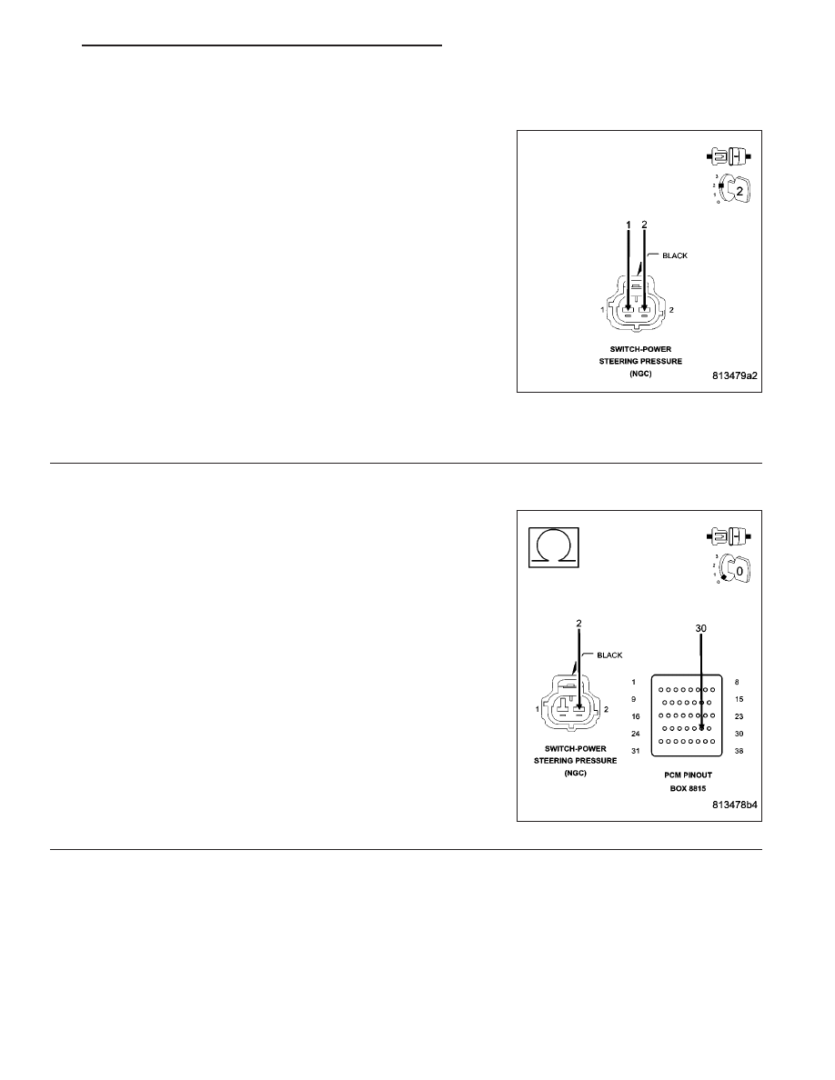
3.

(K66) P/S SWITCH SIGNAL CIRCUIT OPEN

Turn the ignition off.

Disconnect the C3 PCM harness connector.

CAUTION: Do not probe the PCM harness connectors. Probing
the PCM harness connectors will damage the PCM terminals
resulting in poor terminal to pin connection. Install Miller Special
Tool #8815 to perform diagnosis.
Measure resistance of (K66) P/S Switch Signal circuit from the Power
Steering Pressure Switch harness connector to the appropriate termi-
nal of special tool #8815.

Is the resistance below 5.0 ohms?

Yes

>> Go To 4

No

>> Repair the open in the (K66) P/S Switch Signal circuit.

Perform the POWERTRAIN VERIFICATION TEST. (Refer
to 9 - ENGINE - STANDARD PROCEDURE)

HB

ENGINE ELECTRICAL DIAGNOSTICS

9 - 583

P0551-POWER STEERING PRESSURE SWITCH PERFORMANCE (CONTINUED)

4.

(K66) P/S SWITCH SIGNAL CIRCUIT SHORTED TO GROUND

Measure the resistance between ground and the (K66) P/S Switch
Signal circuit in the Switch connector.

Is the resistance below 100 ohms?

Yes

>> Repair the short to ground in the (K66) P/S Switch Signal

circuit.

Perform the POWERTRAIN VERIFICATION TEST. (Refer
to 9 - ENGINE - STANDARD PROCEDURE)

No

>> Go To 5

5.

(Z988) GROUND CIRCUIT OPEN

Measure the resistance between Ground and the (Z988) Ground cir-
cuit in the Power Steering Pressure Switch connector.

Is the resistance below 100 ohms?

Yes

>> Go To 6

No

>> Repair the open in the (Z988) Ground circuit.

Perform the POWERTRAIN VERIFICATION TEST. (Refer
to 9 - ENGINE - STANDARD PROCEDURE)

6.

PCM

NOTE: Before continuing, check the PCM harness connector terminals for corrosion, damage, or terminal
push out. Repair as necessary.
Using the schematics as a guide, inspect the wire harness and connectors. Pay particular attention to all Power and
Ground circuits.

Were there any problems found?

Yes

>> Repair as necessary.

Perform the POWERTRAIN VERIFICATION TEST. (Refer to 9 - ENGINE - STANDARD PROCEDURE)

No

>> Replace and program the Powertrain Control Module per Service Information.

Perform the POWERTRAIN VERIFICATION TEST. (Refer to 9 - ENGINE - STANDARD PROCEDURE)

9 - 584

ENGINE ELECTRICAL DIAGNOSTICS

HB

P0562-BATTERY VOLTAGE LOW

HB

ENGINE ELECTRICAL DIAGNOSTICS

9 - 585

P0562-BATTERY VOLTAGE LOW (CONTINUED)

For the Engine circuit diagram (Refer to 9 - ENGINE - SCHEMATICS AND DIAGRAMS).

For a complete wiring diagram Refer to Section 8W.

When Monitored:
The engine running. The engine speed greater than 1000 RPM.

Set Condition:
Battery voltage is 1 volt less than desired voltage for a set period of time. One Trip Fault. ETC light is flashing.

Possible Causes

RESISTANCE IN THE (A1) BATTERY POSITIVE CIRCUIT

RESISTANCE IN THE GENERATOR CASE GROUND

GENERATOR OPERATION

(K20) GENERATOR FIELD CONTROL CIRCUIT OPEN

(K20) GENERATOR FIELD CONTROL CIRCUIT SHORTED TO GROUND

(Z20) GROUND CIRCUIT OPEN

PCM

Always perform the Pre-Diagnostic Troubleshooting procedure before proceeding. (Refer to 9 - ENGINE -
DIAGNOSIS AND TESTING).

Diagnostic Test

1.

ACTIVE DTC

NOTE: Make sure the Battery is in good condition. Using the Midtronics Battery Tester, test the Battery
before continuing.

NOTE: Inspect the vehicle for after market accessories that may exceed the Generator System output.
Turn the ignition off.

NOTE: Make sure the generator drive belt is in good operating condition.

NOTE: Inspect the fuses in the IPM. If an open fuse is found, use the wire diagram/schematic as a guide,
inspect the wiring and connectors for damage.
Ignition on, engine not running.

With the scan tool, read DTCs.

Is the DTC active at this time?

Yes

>> Go To 2

No

>> Refer to the INTERMITTENT CONDITION Diagnostic Procedure.

Perform the POWERTRAIN VERIFICATION TEST. (Refer to 9 - ENGINE - STANDARD PROCEDURE)

9 - 586

ENGINE ELECTRICAL DIAGNOSTICS

HB


Content   ..  894  895  896  897   ..