Dodge Durango (HB). Manual - part 874


  Index      Dodge     Dodge Durango (HB) - service repair manual 2005 year


Search            


Content   ..  872  873  874  875   ..


Dodge Durango (HB). Manual - part 874


P0453-NVLD PRESSURE SWITCH STUCK OPEN (CONTINUED)

6.

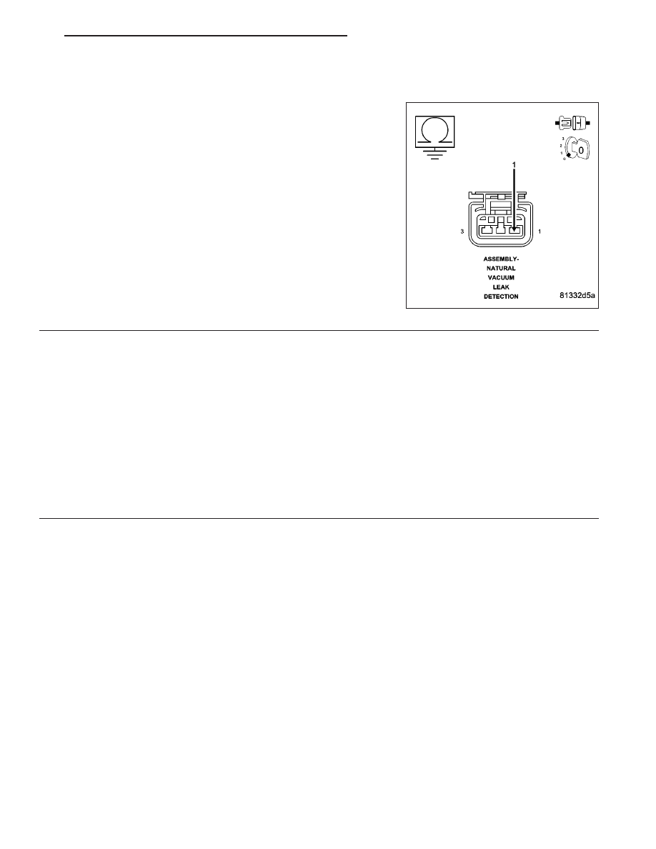
(Z938) GROUND CIRCUIT OPEN

Measure the resistance between the (Z938) Ground circuit and
ground.

Is the resistance below 5.0 ohms?

Yes

>> Go To 7

No

>> Repair the open in the (Z938) Ground circuit.

Perform the POWERTRAIN VERIFICATION TEST. (Refer
to 9 - ENGINE - STANDARD PROCEDURE)

7.

PCM

NOTE: Before continuing, check the PCM harness connector terminals for corrosion, damage, or terminal
push out. Repair as necessary.
Using the schematics as a guide, inspect the wire harness and connectors. Pay particular attention to all Power and
Ground circuits.

Were there any problems found?

Yes

>> Repair as necessary.

Perform the POWERTRAIN VERIFICATION TEST. (Refer to 9 - ENGINE - STANDARD PROCEDURE)

No

>> Replace and program the Powertrain Control Module per Service Information.

Perform the POWERTRAIN VERIFICATION TEST. (Refer to 9 - ENGINE - STANDARD PROCEDURE)

HB

ENGINE ELECTRICAL DIAGNOSTICS

9 - 495

P0455-EVAP PURGE SYSTEM LARGE LEAK

9 - 496

ENGINE ELECTRICAL DIAGNOSTICS

HB

P0455-EVAP PURGE SYSTEM LARGE LEAK (CONTINUED)

For the Engine circuit diagram (Refer to 9 - ENGINE - SCHEMATICS AND DIAGRAMS).

For a complete wiring diagram Refer to Section 8W.

Theory of Operation

The theory behind the Natural Vacuum Leak Detection (NVLD) is adherence to the Ideal Gas Law. Pressure in a
sealed vessel will change linearly as a function of the temperature of the gas in the vessel. Even small leaks will
allow the pressure in the vessel to come to equilibrium with the atmospheric pressure. After key-off and a calibrated
amount of time, cool down from operating temperatures or diurnal ambient temperature the system pressure will
force the system to go negative or draw a vacuum if there is no leak. When the vacuum level reaches 1” H2O (0.25
KPA) the NVLD vacuum switch closes. This sends a signal to the NGC freezing a timer and registering a pass. If
a switch closure is not detected an assessment of leak size will be made.

When Monitored:
Engine Running. Cold start test. Fuel Level greater than 12%. Ambient Temperature between 4°C and 32°C
(39°F and 89°F) Close Loop fuel system. Test runs when small leak test is maturing.

Set Condition:
The PCM activates the EVAP Purge Solenoid to pull the EVAP system into a vacuum to close the NVLD
switch. Once the NVLD switch is closed, the PCM turns the EVAP Purge solenoid off to seal the EVAP system.
If the NVLD switch reopens before the calibrated amount of time for a Large leak an error is detected. Two
Trip Fault. Three good trips to turn off the MIL.

Possible Causes

EVAP PURGE SYSTEM LEAK

EVAP PURGE SOLENOID

NVLD SWITCH

Always perform the Pre-Diagnostic Troubleshooting procedure before proceeding. (Refer to 9 - ENGINE -
DIAGNOSIS AND TESTING).

Diagnostic Test

1.

ACTIVE DTC

Check for any related TSBs before continuing.

NOTE: Since a hot vehicle can conceal a leak, it is best to perform this test at room temperature.

NOTE: A loose gas cap could have caused this DTC to set. Make sure gas cap is tight and in good condi-
tion. Ensure the gas cap meets OEM specifications.
Ignition on, engine not running.

With a scan tool, read DTCs and record the related Freeze Frame data.

Is the DTC active at this time?

Yes

>> Go To 2

No

>> Refer to the INTERMITTENT CONDITION Diagnostic Procedure.

Perform the POWERTRAIN VERIFICATION TEST. (Refer to 9 - ENGINE - STANDARD PROCEDURE)

HB

ENGINE ELECTRICAL DIAGNOSTICS

9 - 497

P0455-EVAP PURGE SYSTEM LARGE LEAK (CONTINUED)

2.

VISUAL AND PHYSICAL INSPECTION

Perform a visual and physical inspection of the entire Evaporative Emission system.

Check for the follow conditions:

- Holes or cracks

- Loose seal points

- Evidence of damaged components

- Incorrect routing of hoses and tubes

- Fuel Cap gasket seal

Were any of the above conditions found?

Yes

>> Repair as necessary.

Perform the POWERTRAIN VERIFICATION TEST. (Refer to 9 - ENGINE - STANDARD PROCEDURE)

No

>> Go To 3

3.

VERIFY EVAPORATIVE EMISSION LEAK

To continue testing you will need Miller Tool #8404A Evaporative Emission Leak Detector (EELD).

WARNING: Keep lit cigarettes, sparks, flames, and other ignition sources away from the test area to prevent
the ignition of explosive gases. Keep the test area well ventilated.

NOTE: The fuel tank should have between 20% and 80% of fuel tank capacity to properly test the Evap
system.
Connect the red power lead of the EELD to the battery positive terminal and the black ground lead to battery neg-
ative terminal.

Block the vent hose of the canister if using the service port.

Connect shop air to the EELD.

Set the smoke/air control switch to AIR.

Insert the tester’s AIR supply tip (clear hose) into the appropriate calibration orifice on the tester’s control panel
(based on DTC leak size).

Press the remote smoke/air start button.

Position the red flag on the air flow meter so it is aligned with the indicator ball.

When the calibration is complete, release the remote button. The EELD flow meter is now calibrated in liters per
minute to the size leak indicated by the DTC set in the PCM.

Install the service port adapter #8404-14 on the vehicle’s service port and block the vent hose of the EVAP Canister
(if equipped) or install the #8404-ADP service adaptor into the filter line.

Connect the Air supply hose from the EELD to the service port (if equipped) or to the #8404-ADP adapter.

Press the remote button to activate AIR flow.

NOTE: Larger volume fuel tanks, lower fuel levels or if the vehicle is equipped with a Flow Management
Valve may indicate high flow and will require 4 to 5 minutes to fill.
Compare the flow meter indicator ball reading to the red flag.

ABOVE the red flag indicates a leak present.

BELOW the red flag indicates a sealed system.

Is the indicator ball above the red flag?

Yes

>> Go To 4

No

>> Refer to the INTERMITTENT CONDITION Diagnostic Procedure.

Perform the POWERTRAIN VERIFICATION TEST. (Refer to 9 - ENGINE - STANDARD PROCEDURE)

9 - 498

ENGINE ELECTRICAL DIAGNOSTICS

HB


Content   ..  872  873  874  875   ..