Index Dodge Dodge Durango (HB) - service repair manual 2005 year
Search
Content .. 820 821 822 823 ..
Dodge Durango (HB). Manual - part 822
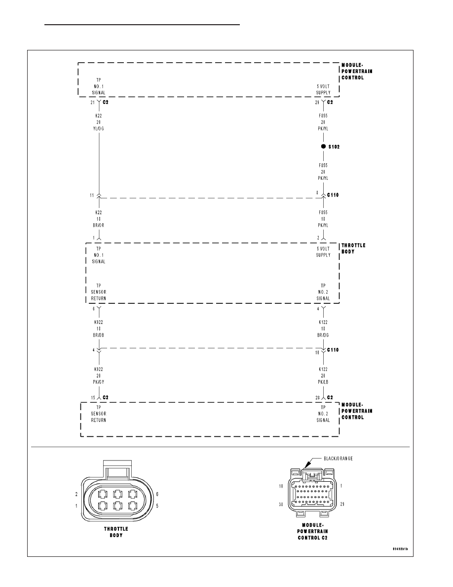
P0221-THROTTLE POSITION SENSOR 2 PERFORMANCE
HB
ENGINE ELECTRICAL DIAGNOSTICS
9 - 287