Dodge Durango (HB). Manual - part 810


  Index      Dodge     Dodge Durango (HB) - service repair manual 2005 year


Search            


Content   ..  808  809  810  811   ..


Dodge Durango (HB). Manual - part 810


P0172-FUEL SYSTEM 1/1 RICH (CONTINUED)

10.

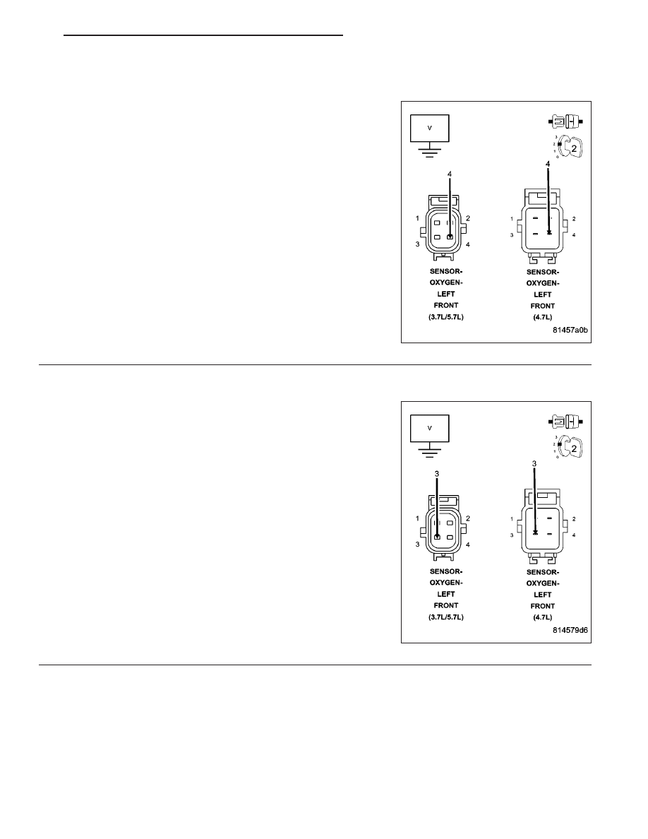
(K41) O2 SENSOR 1/1 SIGNAL CIRCUIT

WARNING: When the engine is operating, do not stand in direct
line with the fan. Do not put your hands near the pulleys, belts, or
fan. Do not wear loose clothing. Failure to follow these instruc-
tions can result in personal injury or death.
Start the engine.

Measure the voltage on the (K41) O2 Sensor 1/1 Signal circuit in the
O2 Sensor harness connector.

Is the voltage above 4.8 volts?

Yes

>> Check the (K41) O2 Sensor 1/1 Signal circuit for damage,

short to ground, open, or short to voltage. Inspect the O2
Sensor connector and the PCM harness connector. If OK,
replace and program the Powertrain Control Module per
Service Information.

Perform the POWERTRAIN VERIFICATION TEST. (Refer
to 9 - ENGINE - STANDARD PROCEDURE)

No

>> Go To 11

11.

(K902) O2 SENSOR UPSTREAM RETURN CIRCUIT

Engine still running.

Measure the voltage on the (K902) O2 Upstream Return circuit in the
1/1 O2 Sensor harness connector.

Is the voltage at 2.5 volts?

Yes

>> Go To 12

No

>> Check the (K902) O2 Upstream Return circuit for damage,

short to ground, open, or short to voltage. Inspect the O2
Sensor connector and the PCM harness connector. If OK,
replace and program the Powertrain Control Module per
Service Information.

Perform the POWERTRAIN VERIFICATION TEST. (Refer
to 9 - ENGINE - STANDARD PROCEDURE)

NOTE: Turn the ignition off before continuing.

HB

ENGINE ELECTRICAL DIAGNOSTICS

9 - 239

P0172-FUEL SYSTEM 1/1 RICH (CONTINUED)

12.

PCM

NOTE: Before continuing, check the PCM harness connector terminals for corrosion, damage, or terminal
push out. Repair as necessary.
Using the schematics as a guide, inspect the wire harness and connectors. Pay particular attention to all Power and
Ground circuits.

Were there any problems found?

Yes

>> Repair as necessary.

Perform the POWERTRAIN VERIFICATION TEST. (Refer to 9 - ENGINE - STANDARD PROCEDURE)

No

>> Replace and program the Powertrain Control Module per Service Information.

Perform the POWERTRAIN VERIFICATION TEST. (Refer to 9 - ENGINE - STANDARD PROCEDURE)

9 - 240

ENGINE ELECTRICAL DIAGNOSTICS

HB

P0174-FUEL SYSTEM 2/1 LEAN

HB

ENGINE ELECTRICAL DIAGNOSTICS

9 - 241

P0174-FUEL SYSTEM 2/1 LEAN (CONTINUED)

For the Engine circuit diagram (Refer to 9 - ENGINE - SCHEMATICS AND DIAGRAMS).

For a complete wiring diagram Refer to Section 8W.

Theory of Operation

The fuel feedback system will maintain a stoiciometric fuel/air mixture, 14.7:1, by modifying the injector pulsewidth
according to the oxygen content of the exhaust gas. The PCM makes short term and long term fuel corrections to
maintain stoiciometric fuel/air ratio for best catalytic converter efficiency. Short term fuel correction is based on
upstream O2 sensor output and is designed for quick engine response. The long term fuel correction compensated
for variations in the engine specifications, sensor tolerances and component aging and is designed to correct rich
and lean conditions over a longer period of time.

When Monitored:
With the engine running in closed loop mode, the ambient/battery temperature above 20 deg. F and altitude
below 8500 ft.

Set Condition:
If the PCM multiplies short term compensation by long term adaptive and a certain percentage is exceeded for
two trips, a freeze frame is stored, the MIL illuminates and a trouble code is stored. Two Trip Fault. Three good
trips to turn off the MIL.

Possible Causes

RESTRICTED FUEL SUPPLY LINE

FUEL PUMP INLET STRAINER PLUGGED

FUEL PUMP MODULE

O2 SIGNAL CIRCUIT

O2 RETURN CIRCUIT

O2 SENSOR HEATER OPERATION

O2 SENSOR

MAP SENSOR OPERATION

ECT SENSOR OPERATION

ENGINE MECHANICAL

FUEL FILTER/PRESSURE REGULATOR (HIGH)

PCM

Always perform the Pre-Diagnostic Troubleshooting procedure before proceeding. (Refer to 9 - ENGINE -
DIAGNOSIS AND TESTING).

Diagnostic Test

1.

ACTIVE DTC

Diagnose all other trouble codes before continuing.

NOTE: Check for contaminants that may have damaged an O2 Sensor: contaminated fuel, unapproved sil-
icone, oil and coolant.
Ignition on, engine not running.

With a scan tool, read DTCs.

Is the DTC active at this time?

Yes

>> Go To 2

No

>> Refer to the INTERMITTENT CONDITION Diagnostic Procedure.

Perform the POWERTRAIN VERIFICATION TEST. (Refer to 9 - ENGINE - STANDARD PROCEDURE)

9 - 242

ENGINE ELECTRICAL DIAGNOSTICS

HB


Content   ..  808  809  810  811   ..