Dodge Durango (HB). Manual - part 787
P0128-THERMOSTAT RATIONALITY (CONTINUED)
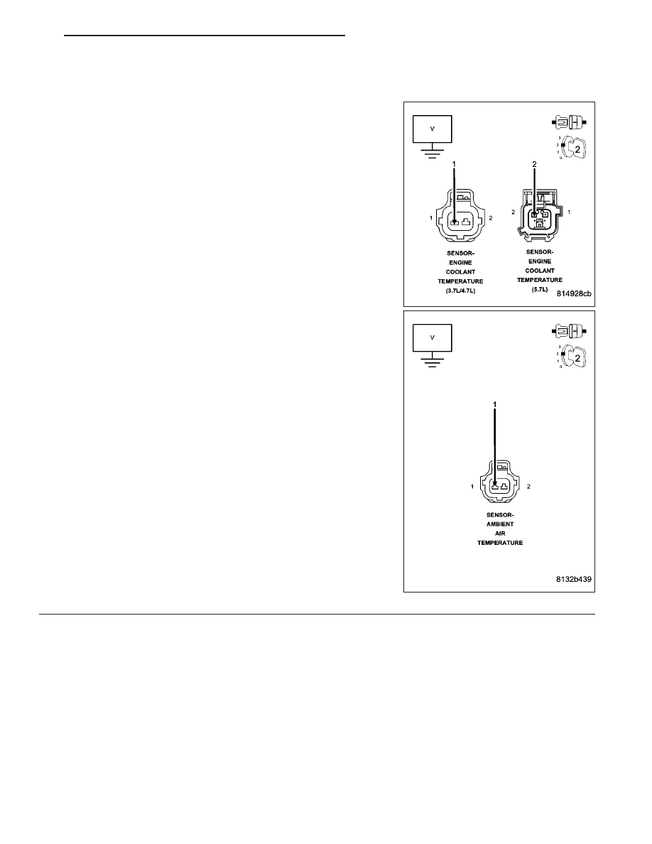
7.
SIGNAL CIRCUIT SHORTED TO BATTERY VOLTAGE
NOTE: Visually inspect both the component and the PCM connec-
tors. Look for damage, partially broken wires and backed out or
corroded terminals
Turn the ignition off.
Disconnect the applicable Temperature Sensor harness connector.
Disconnect the C2 FCM harness connector and the C2 PCM harness
connector.
Ignition on, engine not running.
Measure the voltage on the (K2) ECT Signal circuit and the (G31) AAT
Signal circuit at the appropriate Temperature Sensor harness connec-
tor.
Is the voltage above 5.2 volts?
Yes
>> Repair the short to battery voltage in the Signal circuit.
Perform the POWERTRAIN VERIFICATION TEST. (Refer
to 9 - ENGINE - STANDARD PROCEDURE)
No
>> Go To 8
HB
ENGINE ELECTRICAL DIAGNOSTICS
9 - 147