Index Dodge Dodge Durango (HB) - service repair manual 2005 year
Search
Content .. 765 766 767 768 ..
Dodge Durango (HB). Manual - part 767
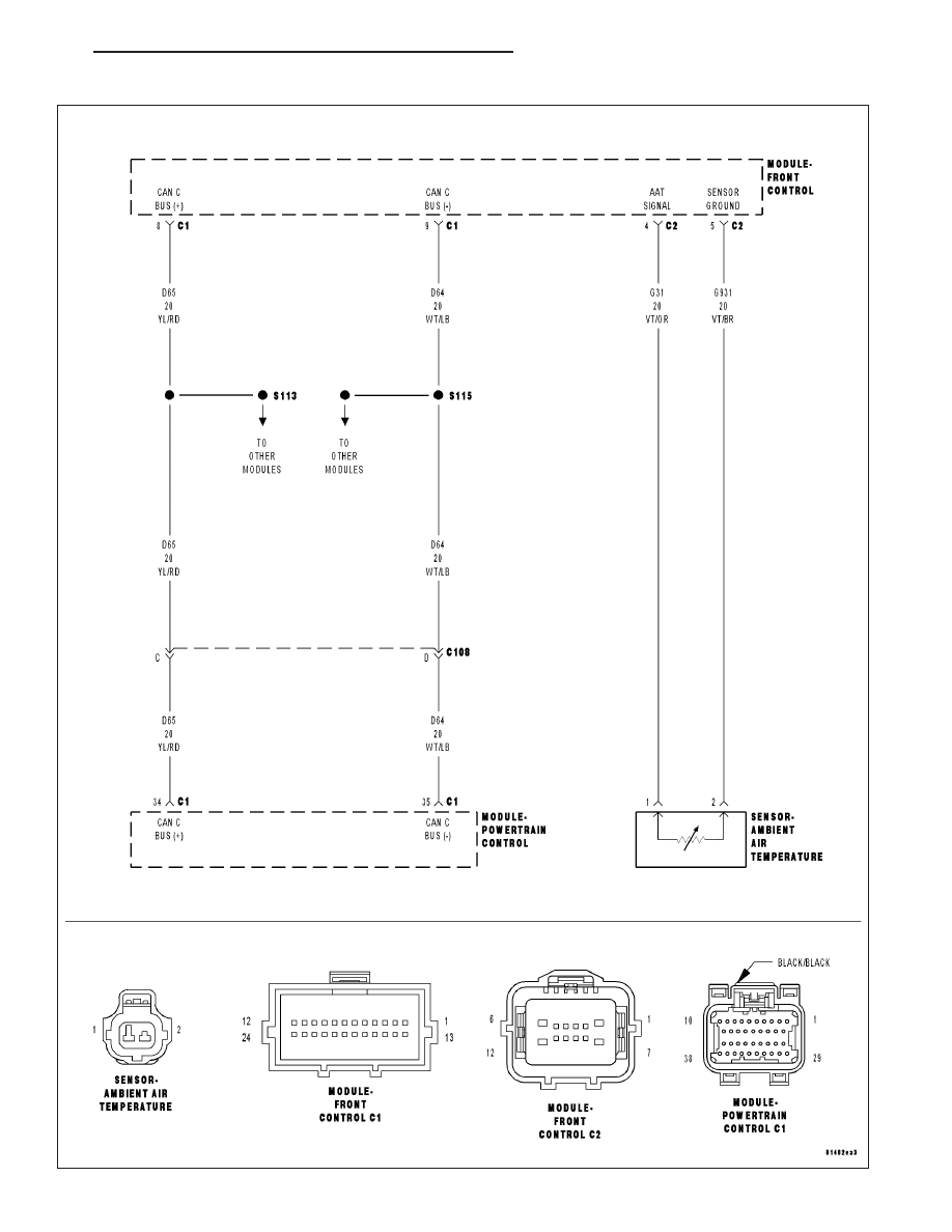
P0072-AMBIENT AIR TEMPERATURE SENSOR CIRCUIT LOW
HB
ENGINE ELECTRICAL DIAGNOSTICS
9 - 67