Dodge Durango (HB). Manual - part 558


  Index      Dodge     Dodge Durango (HB) - service repair manual 2005 year


Search            


Content   ..  556  557  558  559   ..


Dodge Durango (HB). Manual - part 558


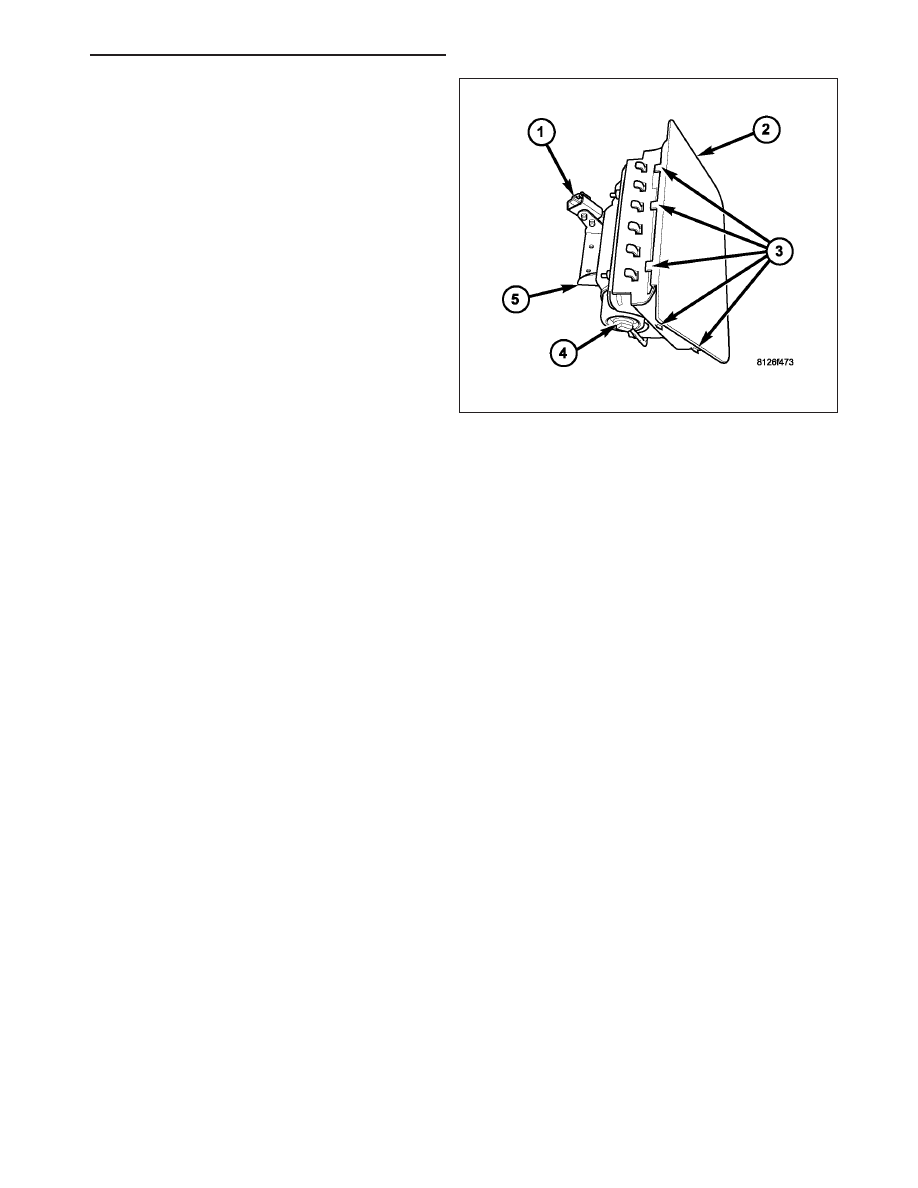
The outboard edges of the airbag door are secured
with integral snap features (3) to the instrument panel
base trim. Located below the passenger airbag door
(2) within the instrument panel is the passenger airbag
unit. The passenger airbag housing fits into a molded
receptacle on the back of the airbag door, where
twelve stamped hook formations on the forward and
rearward edges of the airbag housing are engaged in
mating small window openings on the forward and
rearward flanges of the receptacle to secure the air-
bag door to the airbag housing. These airbag door
fasteners and mounting provisions are all concealed
beneath the instrument panel base trim. The passen-
ger airbag unit is secured by two screws through a
stamped mounting bracket (5) to the instrument panel
structural support.

The passenger airbag unit used in this model is a multistage, Next Generation-type that complies with revised fed-
eral airbag standards to deploy with less force than those used in some prior models. The passenger airbag unit
consists of a stamped and welded metal housing, the airbag cushion, the airbag inflator, and a stamped metal air-
bag cushion retainer plate that is secured to the airbag housing with four studs and nuts. The airbag housing con-
tains the airbag inflator and the folded airbag cushion. An approximately 80 centimeter (31.5 inch) wide by 90
centimeter (35.5 inch) high rectangular fabric cushion is used.

The airbag inflator (4) is a non-azide, pyrotechnic-type unit that is secured to and sealed within the airbag housing.
A short four-wire pigtail harness with a keyed, yellow connector insulator (1) connects the two inflator initiators to the
vehicle electrical system through a dedicated take out and connector of the instrument panel wire harness.

The passenger airbag includes the airbag door. This unit cannot be repaired, and must be replaced if deployed,
faulty, or in any way damaged.

OPERATION

The multistage passenger airbag is deployed by electrical signals generated by the Occupant Restraint Controller
(ORC) through the passenger airbag squib 1 and squib 2 circuits to the two initiators in the airbag inflator. By using
two initiators, the airbag can be deployed at multiple levels of force. The force level is controlled by the ORC to suit
the monitored impact conditions by providing one of three delay intervals between the electrical signals provided to
the two initiators. The longer the delay between these signals, the less forcefully the airbag will deploy.

When the ORC sends the proper electrical signals to each initiator, the electrical energy generates enough heat to
initiate a small pyrotechnic charge which, in turn ignites chemical pellets within the inflator. Once ignited, these
chemical pellets burn rapidly and produce a large quantity of inert gas. The inflator is sealed to the airbag cushion
and a diffuser in the inflator directs all of the inert gas into the airbag cushion, causing the cushion to inflate. As the
cushion inflates, the passenger airbag door will split at predetermined tear seam lines concealed on the inside sur-
face of the door, then the door will pivot up over the top of the instrument panel and out of the way. Following an
airbag deployment, the airbag cushion quickly deflates by venting the inert gas through vent holes within the fabric
used to construct the back (windshield side) of the airbag cushion.

Typically, both initiators are used during an airbag deployment event. However, it is possible for only one initiator to
be used during a deployment due to an airbag system fault; therefore, it is necessary to always confirm that both
initiators have been used in order to avoid the improper disposal of potentially live pyrotechnic materials. (Refer to
8 - ELECTRICAL/RESTRAINTS - STANDARD PROCEDURE - SERVICE AFTER A SUPPLEMENTAL RESTRAINT
DEPLOYMENT).

HB

RESTRAINTS - SERVICE INFORMATION

8O - 501

REMOVAL

WARNING: To avoid personal injury or death, on vehicles equipped with airbags, disable the supplemental
restraint system before attempting any steering wheel, steering column, airbag, occupant classification sys-
tem, seat belt tensioner, impact sensor, or instrument panel component diagnosis or service. Disconnect
and isolate the battery negative (ground) cable, then wait two minutes for the system capacitor to discharge
before performing further diagnosis or service. This is the only sure way to disable the supplemental
restraint system. Failure to take the proper precautions could result in accidental airbag deployment.

WARNING: To avoid personal injury or death, when removing a deployed airbag, rubber gloves, eye protec-
tion, and a long-sleeved shirt should be worn. There may be deposits on the airbag unit and other interior
surfaces. In large doses, these deposits may cause irritation to the skin and eyes.

NOTE: The following procedure is for replacement of a faulty or damaged passenger airbag. If the airbag is
faulty or damaged, but not deployed, review the recommended procedures for handling non-deployed sup-
plemental restraints. (Refer to 8 - ELECTRICAL/RESTRAINTS - STANDARD PROCEDURE - HANDLING NON-
DEPLOYED SUPPLEMENTAL RESTRAINTS). If the passenger airbag has been deployed, review the
recommended procedures for service after a supplemental restraint deployment before removing the airbag
from the vehicle. (Refer to 8 - ELECTRICAL/RESTRAINTS - STANDARD PROCEDURE - SERVICE AFTER A
SUPPLEMENTAL RESTRAINT DEPLOYMENT).

CAUTION: Be certain to take the proper precautions to prevent the instrument panel top pad from receiving
cosmetic damage from the passenger airbag housing during the following procedures.

1. Disconnect and isolate the battery negative cable.

Wait two minutes for the system capacitor to dis-
charge before further service.

2. Remove the defroster grille from the top of the

instrument panel. (Refer to 23 - BODY/INSTRU-
MENT PANEL/DEFROSTER GRILLE - REMOVAL).

3. Remove the glove box from the instrument panel.

(Refer

to

23

-

BODY/INSTRUMENT

PANEL/

GLOVE BOX - REMOVAL).

4. Reach up into the instrument panel glove box

opening (2) and through the access holes (1) to
remove the two screws (4) that secure the passen-
ger airbag bracket (3) to the instrument panel sup-
port structure.

5. Using a trim stick or another suitable wide flat-

bladed tool, gently pry the forward and side edges
of the passenger airbag door away from the top of
the instrument panel far enough to disengage the
snap features on the door from the receptacles in the instrument panel top pad.

6. Pull the passenger airbag out of the instrument panel far enough to access and disconnect the instrument panel

wire harness connector from the airbag inflator pigtail wire connector on the right side of the airbag mounting
bracket. To disconnect the connector:

a. Slide the red Connector Position Assurance (CPA) lock on the top of the connector toward the side of the

connector.

b. Depress the connector latch tab and pull the two halves of the connector straight away from each other.

7. Remove the passenger airbag from the instrument panel as a unit.

8O - 502

RESTRAINTS - SERVICE INFORMATION

HB

INSTALLATION

WARNING: To avoid personal injury or death, on vehicles equipped with airbags, disable the supplemental
restraint system before attempting any steering wheel, steering column, airbag, occupant classification sys-
tem, seat belt tensioner, impact sensor, or instrument panel component diagnosis or service. Disconnect
and isolate the battery negative (ground) cable, then wait two minutes for the system capacitor to discharge
before performing further diagnosis or service. This is the only sure way to disable the supplemental
restraint system. Failure to take the proper precautions could result in accidental airbag deployment.

WARNING: To avoid personal injury or death, use extreme care to prevent any foreign material from enter-
ing the passenger airbag, or becoming entrapped between the passenger airbag cushion and the passenger
airbag door. Failure to observe this warning could result in occupant injuries upon airbag deployment.

WARNING: To avoid personal injury or death, the passenger airbag door must never be painted. Replace-
ment passenger airbags are serviced with doors in the original colors. Paint may change the way in which
the material of the airbag door responds to an airbag deployment. Failure to observe this warning could
result in occupant injuries upon airbag deployment.

NOTE: The following procedure is for replacement of a faulty or damaged passenger airbag. If the airbag is
faulty or damaged, but not deployed, review the recommended procedures for handling non-deployed sup-
plemental restraints. (Refer to 8 - ELECTRICAL/RESTRAINTS - STANDARD PROCEDURE - HANDLING NON-
DEPLOYED SUPPLEMENTAL RESTRAINTS). If the passenger airbag has been deployed, review the
recommended procedures for service after a supplemental restraint deployment before removing the airbag
from the vehicle. (Refer to 8 - ELECTRICAL/RESTRAINTS - STANDARD PROCEDURE - SERVICE AFTER A
SUPPLEMENTAL RESTRAINT DEPLOYMENT).

CAUTION: Be certain to take the proper precau-
tions to prevent the instrument panel top pad from
receiving cosmetic damage from the passenger
airbag housing during the following procedures.

1. Position the passenger airbag unit onto the instru-

ment panel.

2. Reconnect the instrument panel wire harness con-

nector for the airbag to the passenger airbag infla-
tor pigtail wire connector on the right side of the
airbag mounting bracket. Be certain that the latch
on the connector and the red Connector Position
Assurance (CPA) lock are each fully engaged.

3. Carefully lower the passenger airbag unit into the

instrument panel, being certain that the airbag
mounting bracket (3) is properly positioned to the
instrument panel support structure.

4. Reach into the glove box opening (2) to install and

tighten the two screws (4) that secure the passenger airbag mounting bracket to the instrument panel support
structure through the access holes (1). Tighten the screws to 6 N·m (55 in. lbs.).

5. Align and insert the rearward tabs of the passenger airbag door into the slots in the instrument panel top pad.

6. Using hand pressure, push down on the forward and side edges of the passenger airbag door over each snap

feature until it snaps into its receptacle in the instrument panel top pad.

7. Reinstall the glove box into the instrument panel. (Refer to 23 - BODY/INSTRUMENT PANEL/GLOVE BOX -

INSTALLATION).

8. Reinstall the defroster grille onto the top of the instrument panel. (Refer to 23 - BODY/INSTRUMENT PANEL/

DEFROSTER GRILLE - INSTALLATION).

HB

RESTRAINTS - SERVICE INFORMATION

8O - 503

9. Do not reconnect the battery negative cable at this time. The supplemental restraint system verification test pro-

cedure should be performed following service of any supplemental restraint system component. (Refer to 8 -
ELECTRICAL/RESTRAINTS - STANDARD PROCEDURE - VERIFICATION TEST).

SEAT BELT BUCKLE

REMOVAL

FRONT

WARNING: To avoid personal injury or death, on vehicles equipped with airbags, disable the supplemental
restraint system before attempting any steering wheel, steering column, airbag, occupant classification sys-
tem, seat belt tensioner, impact sensor, or instrument panel component diagnosis or service. Disconnect
and isolate the battery negative (ground) cable, then wait two minutes for the system capacitor to discharge
before performing further diagnosis or service. This is the only sure way to disable the supplemental
restraint system. Failure to take the proper precautions could result in accidental airbag deployment.

WARNING: To avoid personal injury or death, during and following any seat belt or child restraint anchor
service, carefully inspect all seat belts, buckles, mounting hardware, retractors, tether straps, and anchors
for proper installation, operation, or damage. Replace any belt that is cut, frayed, or torn. Straighten any
belt that is twisted. Tighten any loose fasteners. Replace any belt that has a damaged or inoperative buckle
or retractor. Replace any belt that has a bent or damaged latch plate or anchor plate. Replace any child
restraint anchor or the unit to which the anchor is integral that has been bent or damaged. Never attempt to
repair a seat belt or child restraint component. Always replace damaged or faulty seat belt and child
restraint components with the correct, new and unused replacement parts listed in the DaimlerChrysler
Mopar Parts Catalog.

1. Disconnect and isolate the battery negative cable.

Wait two minutes for the system capacitor to dis-
charge before further service.

2. Remove the front seat and seat track from the floor

panel as a unit. (Refer to 23 - BODY/SEATS/SEAT
- FRONT - REMOVAL).

3. Remove the screws that secure the seat cushion

side shield to the inboard side of the seat cushion
frame (3) and remove the shield.

4. Remove the nut (2) that secures the front seat belt

buckle anchor to the stud near the back of the
inboard seat cushion frame.

5. Remove the buckle from the seat.

8O - 504

RESTRAINTS - SERVICE INFORMATION

HB


Content   ..  556  557  558  559   ..