Dodge Durango (HB). Manual - part 493


  Index      Dodge     Dodge Durango (HB) - service repair manual 2005 year


Search            


Content   ..  491  492  493  494   ..


Dodge Durango (HB). Manual - part 493


B1B83-PASSENGER SEAT WEIGHT SENSOR 4 - LEFT REAR INPUT CIRCUIT LOW (CONTINUED)

8.

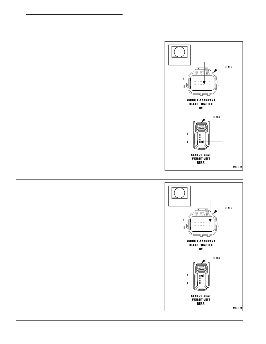
CHECK (R705) LT-RR SEAT WEIGHT SENSOR SIGNAL CIRCUIT FOR AN OPEN

Measure the resistance of the (R705) LT-RR Seat Weight Sensor Sig-
nal circuit between the OCM C2 connector and the Left-Rear Seat
Weight Sensor connector.

Is the resistance below 5.0 ohms?

Yes

>> Replace the Left-Rear Seat Weight Sensor in accordance

with the Service Information. Perform OCS VERIFICATION
TEST - VER 1. If DTC B1B83-PASSENGER SEAT
WEIGHT SENSOR 4 - LEFT REAR INPUT CIRCUIT LOW
returns active, replace the OCM in accordance with the
Service Information.

Perform OCS VERIFICATION TEST - VER 1.

No

>>

NOTE: Do not attempt to repair the Seat Harness. Replace the
Seat Harness if the condition inspecting or testing for is present
in the Seat Harness.

Replace the Passenger Seat Harness in accordance with
the Service Information.

Perform OCS VERIFICATION TEST - VER 1.

9.

CHECK (R701) SEAT WEIGHT SENSOR 5 VOLT CIRCUIT FOR
AN OPEN

WARNING: To avoid personal injury or death, turn the ignition off,
disconnect the battery and wait two minutes before proceeding.
Disconnect the OCM C2 connector.

Measure the resistance of the (R701) Seat Weight Sensor 5 Volt cir-
cuit between the OCM C2 connector and the Left-Rear Seat Weight
Sensor connector.

Is the resistance below 5.0 ohms?

Yes

>> Replace the OCM in accordance with the Service Informa-

tion.

Perform OCS VERIFICATION TEST - VER 1.

No

>>

NOTE: Do not attempt to repair the Seat Harness. Replace the
Seat Harness if the condition inspecting or testing for is present
in the Seat Harness.

Replace the Passenger Seat Harness in accordance with
the Service Information.

Perform OCS VERIFICATION TEST - VER 1.

HB

RESTRAINTS - ELECTRICAL DIAGNOSTICS

8O - 241

B1B83-PASSENGER SEAT WEIGHT SENSOR 4 - LEFT REAR INPUT CIRCUIT LOW (CONTINUED)

10.

TEST FOR INTERMITTENT CONDITION

With the scan tool, record and erase all DTCs from all Airbag modules.

If any ACTIVE codes are present they must be resolved before diag-
nosing any stored codes.

WARNING: To avoid personal injury or death, turn the ignition off,
disconnect the battery and wait two minutes before proceeding.
Using the wiring diagram/schematic as a guide, inspect the wiring and
connectors.

Look for chaffed, pierced, pinched, or partially broken wires and bro-
ken, bent, pushed out, spread, corroded, or contaminated terminals.

The following additional checks may assist you in identifying a possi-
ble intermittent problem.

Reconnect any disconnected components and harness connector.

WARNING: To avoid personal injury or death, turn the ignition on,
then reconnect the battery.
With the scan tool, monitor active codes as you work through the fol-
lowing steps.

WARNING: To avoid personal injury or death, maintain a safe distance from all airbags while performing the
following steps.
Wiggle the wiring harness and connectors of the related airbag circuit or component.

If codes are related to the Driver Airbag circuits, rotate the steering wheel from stop to stop.

If only stored codes return, continue the test until the problem area has been isolated.

In the previous steps you have attempted to recreate the conditions responsible for setting the active DTC in ques-
tion.

Does the scan tool display any ACTIVE DTCs?

Yes

>> Select appropriate symptom from Symptom List.

No

>> No problem found at this time. Erase all codes before returning vehicle to customer.

8O - 242

RESTRAINTS - ELECTRICAL DIAGNOSTICS

HB

B1B84-PASSENGER SEAT WEIGHT SENSOR 4 - LEFT REAR INPUT CIRCUIT HIGH

HB

RESTRAINTS - ELECTRICAL DIAGNOSTICS

8O - 243

B1B84-PASSENGER SEAT WEIGHT SENSOR 4 - LEFT REAR INPUT CIRCUIT HIGH (CONTINUED)

For the Occupant Classification System circuit diagram (Refer to 8 - ELECTRICAL/RESTRAINTS - SCHEMATICS
AND DIAGRAMS).

For a complete wiring diagram Refer to Section 8W.

When Monitored:
While the CAN bus ignition status is in IGN_RUN, the module checks the sensor input ranges.

Set Condition:
If the module detects that the sensor input is greater than 96 ± 0.6% of the (R701) Seat Weight Sensor 5 Volt
circuit voltage.

Possible Causes

PASSENGER SEAT HARNESS IMPROPERLY ROUTED

PASSENGER SEAT HARNESS WIRES CHAFFED, PIERCED, PINCHED, PARTIALLY BROKEN

PASSENGER SEAT HARNESS CONNECTOR TERMINALS BROKEN, BENT PUSHED OUT, SPREAD,
CORRODED, CONTAMINATED

(R705) LT-RR SEAT WEIGHT SENSOR SIGNAL CIRCUIT SHORTED TO VOLTAGE

(R705) LT-RR SEAT WEIGHT SENSOR SIGNAL CIRCUIT SHORTED TO (R701) SEAT WEIGHT SENSOR 5
VOLT CIRCUIT

(R728) SEAT WEIGHT SENSOR GROUND CIRCUIT OPEN

LEFT-REAR SEAT WEIGHT SENSOR

OCCUPANT CLASSIFICATION MODULE (OCM)

Diagnostic Test

1.

CHECK FOR ACTIVE INTERNAL FAULTS, IGNITION FAULTS, & BATTERY FAULTS IN THE OCCUPANT
CLASSIFICATION MODULE (OCM)

NOTE: Ensure the battery is fully charged.

NOTE: When reconnecting Airbag system components, the igni-
tion must be turned off and the battery must be disconnected.
Turn the ignition on, then off, and then on again.

With the scan tool, read Occupant Classification Module (OCM) DTCs.

Does the scan tool display any active DTCs relating to internal
faults, ignition faults, or battery faults?

Yes

>> Diagnose and repair the DTCs. Refer to the Table of Con-

tents in this Section for a complete list of symptoms.

No

>> Go To 2

8O - 244

RESTRAINTS - ELECTRICAL DIAGNOSTICS

HB


Content   ..  491  492  493  494   ..