Dodge Durango (HB). Manual - part 429


  Index      Dodge     Dodge Durango (HB) - service repair manual 2005 year


Search            


Content   ..  427  428  429  430   ..


Dodge Durango (HB). Manual - part 429


The power seat system for this vehicle includes the
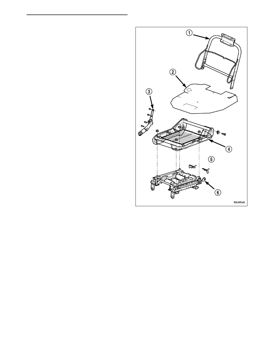
following major components:

Power Seat Adjuster - Depending on the
seat,

four-way

or

eight-way

power,

the

adjuster (6) may be equipped with up to four
electric motors.
There are three reversible motors that operate
the power seat adjuster. The motors are con-
nected to worm-drive gearboxes that move the
seat adjuster through a combination of screw-
type drive units.
The front and rear of a seat are operated by
different motors. They can be raised or low-
ered independently of each other. When the
center seat switch is pushed in the Up or
Down direction, both the front and rear motors
operate in unison. The forward/rearward motor
is operated by pushing the center seat switch
in the Forward or Rearward direction, which
moves the entire seat in the selected direction
on all models.
Each motor contains a self-resetting circuit
breaker to protect it from overload. Consecu-
tive or frequent resetting of the circuit breakers
must not be allowed to continue, or the motors
may be damaged.
The power seat adjuster cannot be repaired,
and is serviced only as a complete unit (Refer
to 23 - BODY/SEATS/SEAT ADJUSTERS -
REMOVAL).

Power Seat Recliner - The power seat
recliner (3) replaces the manual seat recliner.
The power seat option includes an electrically
operated power seat back recliner mechanism.
The power seat recliner switch is integral to
the power seat switch assembly, but is actu-
ated with a separate switch knob.
The power seat recliner motor assembly is
mounted in the place of a seat hinge on the
outboard side of the seat. The upper hinge
plate of the power seat recliner mechanism is
secured with two screws to the seat back
frame and is concealed beneath the seat back
trim cover and padding. The lower hinge plate
and the motor and drive unit of the power seat
recliner

mechanism

is

secured

with

two

screws to the seat cushion frame, and is con-
cealed by the outboard seat cushion side
shield.
The power seat recliner motor cannot be
repaired. If the unit is faulty or damaged, it
must be replaced.

Power Seat Switches - Two power seat switches are used per vehicle if equipped with power seats. One
seat switch is used for each front seat. Each switch is mounted in the appropriate seat cushion side shield.
Refer to the appropriate power seat switch later in this section for additional information.

HB

POWER SEATS - SERVICE INFORMATION

8N - 229

MEMORY SEAT SYSTEM

An electronic memory seat system is available on certain models. The memory system is able to store and recall all
driver side power seat positions, and the drivers side view mirror positions. The system can be set for two different
drivers. On vehicles with a factory installed radio connected to the Programmable Communications Interface (PCI)
data bus network, the memory system is also able to store and recall up to twenty radio station presets (ten AM and
ten FM), also for two drivers. The memory system also will store and recall the last station listened to for each
driver, even if it is not one of the twenty preset stations.

The memory system will automatically recall all of these settings when a button of the memory switch is depressed,
or when the doors are unlocked using the Remote Keyless Entry (RKE) transmitter (if enabled). If the vehicle has
more than two drivers the RKE transmitter recall of memory features can be disabled. This is a customer program-
mable feature of the overhead console. Refer to the Overhead Console section of this manual for additional infor-
mation.

The memory system also has a easy exit feature that will move the driver seat rearward 55 millimeters or to the end
of its travel, whichever occurs first, when the key is removed from the ignition switch lock cylinder. This is a cus-
tomer programmable feature of the overhead console. Refer to the Overhead Console section of this manual for
additional information.

The memory system includes the following components:

Memory Selector Switch - located in the driver door trim panel.

Driver Memory Mirror Module (DMMM) - located in the driver door, behind the trim panel.

Passenger Memory Mirror Module (PMMM) - located in the passenger door, behind the trim panel.

Position Potentiometers - Drivers Mirror - The potentiometer is permanently installed on the drivers side
view mirror motor. This potentiometer is used to provide a reference signal to the memory heated seat mir-
ror module, letting the module know the exact position of the mirror.

Sentry Key Remote Entry Module (SKREEM) - located at ignition key cylinder.

Remote Keyless Entry (RKE) Transmitter - located with ignition key.

Memory Seat Module (MSM) - located underneath the driver seat and also controls the Adjustable Pedals.

Position Potentiometers - Seat Track - These potentiometers are permanently installed in each of the
power seat track motors. They are used to provide a reference signal to the memory heated seat mirror
module, letting the module know the exact position of the seat cushion and recliner.

Radio - located in the instrument panel center stack.

Automatic Temperature Control (ATC) - located in the instrument panel center stack.

Certain functions and features of the memory system rely upon resources shared with other electronic modules in
the vehicle over the Controller Area Network (CAN) bus. The CAN bus allows the sharing of sensor information.
This helps to reduce wire harness complexity, internal controller hardware, and component sensor current loads. At
the same time, this system provides increased reliability, enhanced diagnostics, and allows the addition of many
new feature capabilities. For diagnosis of these electronic modules or of the CAN bus, the use of a scan tool and
the proper diagnostic information are needed.

OPERATION

POWER SEAT SYSTEM

The power seat system receives battery current through a 40 amp fuse in the Power Distribution Center (PDC) and
a 20 amp circuit breaker in the junction block so that the power seats remain operational, regardless of the ignition
switch position.

When a power seat switch is actuated, a battery feed and a ground path are applied through the power seat switch
contacts to the appropriate motor or motors. The motor and drive unit operate to move the seat in the selected
direction until the switch is released, or until the travel limit of the power seat track is reached. When the switch is
moved in the opposite direction, the battery feed and ground path to the motor is reversed through the switch con-
tacts. This causes the motor to run in the opposite direction.

When the recliner switch control knob is actuated, a resistance signal is sent to the appropriate Door Module via
hard wired connections. The door module then sends the request to the Memory Seat Module (MSM) via the Con-
troller Area Network (CAN) bus circuit. The MHSAPM is responsible for the 12v battery feed and ground path to the

8N - 230

POWER SEATS - SERVICE INFORMATION

HB

power seat recliner adjuster motor. The adjuster motor operates to move the recliner mechanism through its drive
unit in the selected direction until the switch is released, or until the travel limit of the adjuster is reached.

The driver side power seat recliner motor used on models equipped with the memory system also has a position
potentiometer integral to the motor assembly, which electronically monitors the motor position.

MEMORY SEAT SYSTEM

The Memory Seat Module (MSM) receives hard wired inputs from the memory set/position switch and the potenti-
ometers, mounted on each of the driver power seat adjuster motors and the driver side view mirror motor. The
programmed software in the module allows it to know where the seat/mirror is located in its designed travel by a
resistance reading generated from the seat adjuster or mirror mounted potentiometer. This way, when the memory
switch is depressed the module will power the seat adjuster or mirror motors until the correct preset location is
achieved. The module will prevent the seat memory recall function from being initiated, if the transmission gear
selector lever is not in the Park or Neutral positions, or if the vehicle is moving. These inputs are monitored over the
Controller Area Network (CAN) bus circuit by the MSM.

A memory setting is saved by pressing the “set” button, then pressing either the memory “1” or “2” button within 5
seconds of pressing the “set” button.

A memory setting is recalled by pressing either the memory “1” or “2” button, or by pressing the unlock button on
a “linked” Remote Keyless Entry (RKE) transmitter.

For driver safety, memorized settings can not be recalled if the transmission is in a position other than Park or the
seat belt is latched.

DIAGNOSIS AND TESTING

MEMORY SEAT SYSTEM

In order to obtain conclusive testing of the power seats with and without the memory system option, the Controller
Area Network (CAN) bus, and all of the electronic modules that provide inputs to, or receive outputs from the mem-
ory system components must be checked. Use a scan tool and the proper diagnostic information to accurately diag-
nose the power seat/memory seat systems.

Note: Vehicles equipped with the memory/heated seat option utilize a low voltage cut-off feature. This fea-
ture turns off the 12v power to the power seat system anytime vehicle voltage is below 11.7v. Be certain to
check the vehicle electrical system for proper voltage anytime the power seat system appears inoperative.

Before any testing of the power seat system is attempted, the battery should be fully-charged.

POWER SEAT ADJUSTER

Operate the power seat switch and move the seat in all direction. The seat should move in each of the selected
directions.

If the power seat adjuster fails to operate in more than one direction, proceed as follows:

1. Check the power seat fuse in the power distribution center. If OK, go to Step 2. If not OK, replace the faulty fuse.

2. Remove the power seat switch from the seat cushion side panel. Check for battery voltage at the fused B(+)

circuit cavity of the power seat switch wire harness connector. If OK, go to Step 3. If not OK, repair the open
circuit to the power distribution center as required.

3. Check for continuity between the ground circuit cavity of the power seat switch wire harness connector and a

good ground. There should be continuity. If OK, go to Step 4. If not OK, repair the open circuit to ground as
required.

4. (Refer to 8 - ELECTRICAL/POWER SEATS/SEAT SWITCH - DIAGNOSIS AND TESTING). If the switch tests

OK, check the wire harness between the power seat switch and the motor. If the circuits check OK, replace the
faulty power seat adjuster assembly. If the circuits are not OK, repair the wire harness as required.

HB

POWER SEATS - SERVICE INFORMATION

8N - 231

POWER SEAT RECLINER

1. Using a scan tool, check for any stored Diagnostic Trouble Codes (DTC’s) in the memory seat module. If DTC’s

are present, use the proper diagnostic information to correct the DTC(s).

2. If the power seat recliner is not operational in any direction, check the power seat circuit breaker, located in the

Integrated Power Module. If OK, go to Step 3.

3. Check for proper battery or electrical system voltage. If the electrical system voltage drops below a predeter-

mined set-point (approximately 11.5v), the power seat system will not function until the proper system voltage
has been restored. If OK, go to Step 4.

4. If the recliner motor is inoperative, apply 12v and a good ground source to the inoperative motor. If the motor

does not operate in either direction replace the recliner motor assembly,

STANDARD PROCEDURE

MEMORY SYSTEM PROGRAMMING

The Memory Heated Seat Mirror Module (MHSMM) interfaces with the RKE vial the Programmable Communication
Interface (PCI) bus. The proper procedure of setting and recalling a memory position using the RKE is as follows:

1. Press memory switch 1 and release to recall memory position 1.

2. Adjust the seat, recliner, set radio station presets and side view mirrors to the desired position.

3. Press momentarily and release memory switch S.

4. Press momentarily and release memory switch 1 or 2.

5. Press and release the LOCK button on one of the RKE transmitters. Do NOT press any switch for 10 seconds.

To program the second driver’s position, repeat the above procedure using memory switch 2. The second RKE
transmitter can be programmed in the same fashion.

Note: The module will abort a recall if the transmission is moved out of park or if any seat movement is
activated whether manually or by memory recall.

To recall either of the programmed positions momentarily press and release either memory selector switch 1 or 2.
If using RKE, just press and release the UNLOCK button on the proper transmitter for either position 1 or 2.

A recall is possible any time the vehicle transmission is in PARK. This condition is monitored by the MHSMM.

8N - 232

POWER SEATS - SERVICE INFORMATION

HB


Content   ..  427  428  429  430   ..