Dodge Durango (HB). Manual - part 407


  Index      Dodge     Dodge Durango (HB) - service repair manual 2005 year


Search            


Content   ..  405  406  407  408   ..


Dodge Durango (HB). Manual - part 407


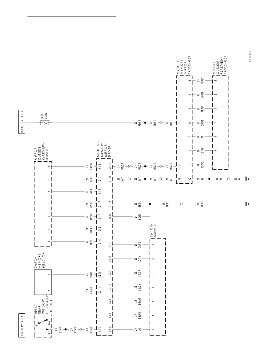
SCHEMATICS AND DIAGRAMS

MEMOR

Y

MIRRORS

SYSTEM

HB

POWER MIRRORS - ELECTRICAL DIAGNOSTICS

8N - 141

POWER MIRRORS - SERVICE INFORMATION

TABLE OF CONTENTS

page

page

POWER MIRRORS - SERVICE INFORMATION

DESCRIPTION

. . . . . . . . . . . . . . . . . . . . . . . . 142

OPERATION

. . . . . . . . . . . . . . . . . . . . . . . . . . 142

DIAGNOSIS AND TESTING

POWER MIRRORS

. . . . . . . . . . . . . . . . . . . 142

MIRROR-INSIDE REARVIEW

DESCRIPTION

. . . . . . . . . . . . . . . . . . . . . . . . 143

OPERATION

. . . . . . . . . . . . . . . . . . . . . . . . . . 143

DIAGNOSIS AND TESTING

AUTOMATIC DAY/NIGHT MIRROR

. . . . . . . . 143

SWITCH-MIRROR

DESCRIPTION

. . . . . . . . . . . . . . . . . . . . . . . . 144

OPERATION

. . . . . . . . . . . . . . . . . . . . . . . . . . 145

DIAGNOSIS AND TESTING

POWER MIRROR SWITCH

. . . . . . . . . . . . . 145

REMOVAL

. . . . . . . . . . . . . . . . . . . . . . . . . . . . 146

INSTALLATION

. . . . . . . . . . . . . . . . . . . . . . . . 146

POWER MIRRORS - SERVICE INFORMATION

DESCRIPTION

AUTOMATIC DAY/NIGHT MIRROR

The automatic day/night mirror system is able to automatically change the reflectance of the inside rear view mirror
in order to reduce the glare of headlamps approaching the vehicle from the rear. The automatic day/night rear view
mirror receives battery current through a fuse in the junction block only when the ignition switch is in the On posi-
tion.

OUTSIDE REAR VIEW MIRROR

The power operated rear view mirrors allow the driver to adjust both outside mirrors electrically from the driver side
front seat position by operating a switch on the driver side front door trim panel. The power mirrors receive a non-
switched battery feed through a fuse in the junction block so that the system will remain operational, regardless of
the ignition switch position.

OPERATION

AUTOMATIC DAY/NIGHT MIRROR

A switch located on the bottom of the automatic day/night mirror housing allows the vehicle operator to select
whether the automatic dimming feature is operational. When the automatic day/night mirror is turned on, the mirror
switch is lighted by an integral Light-Emitting Diode (LED). The mirror will automatically disable its self-dimming
feature whenever the vehicle is being driven in reverse.

DIAGNOSIS AND TESTING

POWER MIRRORS

For complete circuit diagrams, refer to the appropriate wiring information.

1. Check the fuses in the Power Distribution Center (PDC) and the junction block. If OK, go to Step 2. If not OK,

repair the shorted circuit or component as required and replace the faulty fuse(s).

2. Check for battery voltage at the fuse in the junction block. If OK, go to Step 3. If not OK, repair the open circuit

to the PDC as required.

8N - 142

POWER MIRRORS - SERVICE INFORMATION

HB

3. Disconnect and isolate the battery negative cable. Remove the driver side power window switch and bezel

assembly and unplug the wire harness connector from the power mirror switch. Connect the battery negative
cable. Check for battery voltage at the fused B(+) circuit cavity in the door wire harness half of the power mirror
switch wire harness connector. If OK, go to Step 4. If not OK, repair the open circuit to the junction block as
required.

4. Disconnect and isolate the battery negative cable. Check for continuity between the ground circuit cavity in the

door wire harness half of the power mirror switch wire harness connector and a good ground. There should be
continuity. If OK, (Refer to 8 - ELECTRICAL/POWER MIRRORS/SIDEVIEW MIRROR - DIAGNOSIS AND TEST-
ING). If not OK, repair open in the ground circuit.

MIRROR-INSIDE REARVIEW

DESCRIPTION

The automatic day/night mirror uses a thin layer of electrochromic material between two pieces of conductive glass
to make up the face of the mirror. When the mirror switch is in the On position, two photocell sensors are used by
the mirror circuitry to monitor external light levels and adjust the reflectance of the mirror.

OPERATION

The ambient photocell sensor is located on the forward-facing (windshield side) of the rear view mirror housing, and
detects the ambient light levels outside of the vehicle. The headlamp photocell sensor is located inside the rear view
mirror housing behind the mirror glass and faces rearward, to detect the level of the light being received at the rear
window side of the mirror. When the circuitry of the automatic day/night mirror detects that the difference between
the two light levels is too great (the light level received at the rear of the mirror is much higher than that at the front
of the mirror), it begins to darken the mirror.

The automatic day/night mirror circuitry also monitors the transmission using an input from the backup lamp circuit.
The mirror circuitry is programmed to automatically disable its self-dimming feature whenever it senses that the
transmission backup lamp circuit is energized.

The automatic day/night mirror is a completely self-contained unit and cannot be repaired. If faulty or damaged, the
entire mirror assembly must be replaced.

DIAGNOSIS AND TESTING

AUTOMATIC DAY/NIGHT MIRROR

For complete circuit diagrams, refer to the appropriate wiring information.

1. Check the fuse in the junction block. If OK, go to Step 2. If not OK, repair the shorted circuit or component as

required and replace the faulty fuse.

2. Turn the ignition switch to the On position. Check for battery voltage at the fuse in the junction block. If OK, go

to Step 3. If not OK, repair the open circuit to the ignition switch as required.

3. Turn the ignition switch to the Off position. Disconnect and isolate the battery negative cable. Unplug the wire

harness connector from the automatic day/night mirror. Connect the battery negative cable. Turn the ignition
switch to the On position. Check for battery voltage at the fused ignition switch output (run/start) circuit cavity of
the automatic day/night mirror wire harness connector. If OK, go to Step 4. If not OK, repair the open circuit to
the junction block as required.

HB

POWER MIRRORS - SERVICE INFORMATION

8N - 143

4. Turn the ignition switch to the Off position. Discon-

nect and isolate the battery negative cable. Check
for continuity between the ground circuit cavity of
the automatic day/night mirror wire harness con-
nector and a good ground. There should be conti-
nuity. If OK, go to Step 5. If not OK, repair the
circuit to ground as required.

5. Connect the battery negative cable. Turn the igni-

tion switch to the On position. Apply the parking
brake. Place the transmission gear selector lever in
the Reverse position. Check for battery voltage at
the backup lamp switch output circuit cavity of the
automatic day/night mirror wire harness connector.
If OK, go to Step 6. If not OK, repair the open cir-
cuit as required.

6. Turn the ignition switch to the Off position. Disconnect the battery negative cable. Plug in the automatic day/night

mirror wire harness connector. Connect the battery negative cable. Turn the ignition switch to the On position.
Place the transmission gear selector lever in the Neutral position. Place the mirror switch in the On (the LED in
the mirror switch is lighted) position. Cover the forward facing ambient photocell sensor to keep out any ambient
light.

Note: The ambient photocell sensor must be covered completely, so that no light reaches the sensor. Use
a finger pressed tightly against the sensor, or cover the sensor completely with electrical tape.

7. Shine a light into the rearward facing headlamp photocell sensor. The mirror glass should darken. If OK, go to

Step 8. If not OK, replace the faulty automatic day/night mirror unit.

8. With the mirror glass darkened, place the transmission gear selector lever in the Reverse position. The mirror

should return to its normal reflectance. If not OK, replace the faulty automatic day/night mirror.

SWITCH-MIRROR

DESCRIPTION

A power mirror switch is located on the driver’s door
trim panel, attached to the window/lock switch. The
power mirror switch includes the following:

Power Mirror Selector Switch - A three-posi-
tion rotary joystick switch selects the right or
left power mirror for adjustment, or turns the
power mirror system Off in the center position.

Power

Mirror

Adjustment

Switch

-

A

momentary joystick directional switch allows
the driver to adjust the selected power mirror
in the Up, Down, Right or Left directions.

8N - 144

POWER MIRRORS - SERVICE INFORMATION

HB


Content   ..  405  406  407  408   ..