Dodge Durango (HB). Manual - part 371
The ambient temperature sensor circuit can also be diagnosed using the following Sensor Test, and Sensor Circuit
Test. If the temperature sensor and circuit are confirmed to be OK, but the temperature display is inoperative or
incorrect, test the mini-trip computer (Refer to 8 - ELECTRICAL/OVERHEAD CONSOLE/COMPASS/MINI-TRIP
COMPUTER - DIAGNOSIS AND TESTING).
SENSOR TEST
1. Turn the ignition switch to the Off position. Disconnect and isolate the battery negative cable. Disconnect the
ambient temperature sensor harness connector.
2. Measure the resistance of the ambient temperature sensor. At - 40° C (- 40° F), the sensor resistance is 336
kilohms. At 55° C (130° F), the sensor resistance is 2.488 kilohms. The sensor resistance should read between
these two values. If OK, refer to Sensor Circuit Test in this group. If not OK, replace the faulty ambient temper-
ature sensor.
SENSOR CIRCUIT TEST
1. Turn the ignition switch to the Off position. Disconnect and isolate the battery negative cable. Disconnect the
wire harness connectors from the ambient temperature sensor and the A/C-heater control.
2. Connect a jumper wire between the two terminals in the body half of the ambient temperature sensor harness
connector.
3. Check for continuity between the sensor return circuit and the ambient temperature sensor signal circuit cavities
of the A/C-heater control harness connector. There should be continuity. If OK, go to Step 4. If not OK, repair the
open sensor return circuit or ambient temperature sensor signal circuit to the ambient temperature sensor as
required.
4. Check for continuity between the ambient temperature sensor signal circuit cavity of the A/C-heater control har-
ness connector and a good ground. There should be no continuity. If OK, test the mini-trip computer (Refer to 8
- ELECTRICAL/OVERHEAD CONSOLE/COMPASS/MINI-TRIP COMPUTER - DIAGNOSIS AND TESTING). If
not OK, repair the shorted ambient temperature sensor signal circuit as required.
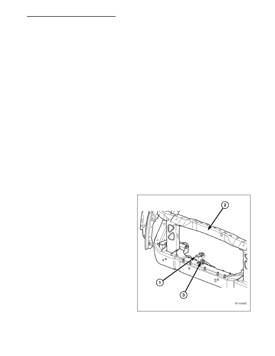
REMOVAL
1. Disconnect and isolate the battery negative cable.
2. Locate the ambient temperature sensor (1), on the
right side of the radiator yoke (2) behind the grille.
3. Disconnect the wire harness connector (3) from the
ambient temperature sensor connector receptacle.
4. Remove the one screw that secures the ambient
temperature sensor bracket to the radiator yoke.
5. Remove the ambient temperature sensor from the
radiator yoke.
HB
OVERHEAD CONSOLE - SERVICE INFORMATION
8M - 37