Dodge Durango (HB). Manual - part 351
WIRING-TRAILER TOW
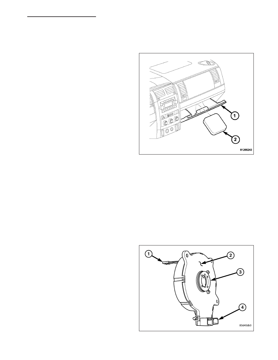
DESCRIPTION
Vehicles equipped with a factory-installed trailer tow
package include an electric trailer brake wiring provi-
sion that terminates at a connector located on top of
the large body harness connection under the instru-
ment panel to the left of the brake pedal, as well as
an electric trailer brake pigtail harness and an instruc-
tion card (2) that are stored in the glove box (1) when
the vehicle is shipped from the factory.
OPERATION
If an aftermarket electric brake controller is used, the electric brake pigtail harness supplied will make installation
easier. The connection (blue 4-way connector) for the harness is located under the instrument panel to the left of
the brake pedal on top of the large body harness connection. Refer to the appropriate wiring information.
The battery line of this harness may be used to charge the trailer battery. However, a battery isolation unit is not
supplied and the trailer battery may discharge the truck battery when the engine is not running. The battery line is
protected by a fuse or a circuit breaker. Refer to the owner’s manual in the vehicle glove box for type, location, and
ampere rating.
CAM-TURN SIGNAL CANCEL
DESCRIPTION
The turn signal cancel cam (3) is concealed within the
steering column. The turn signal cancel cam consists
of two lobes on a molded plastic ring that is snapped
into the lower hub of the clockspring rotor. The clock-
spring mechanism provides turn signal cancellation as
well as a constant electrical connection between the
horn switch, driver airbag, speed control switches, and
remote radio switches on the steering wheel and the
instrument panel wire harness on the steering column.
The housing of the clockspring (2) is secured to the
multi-function switch mounting housing on the steering
column and remains stationary. The rotor of the clock-
spring, including the turn signal cancel cam lobes
rotate with the steering wheel.
The turn signal cancel cam is serviced as a unit with
the clockspring and cannot be repaired. If faulty or
damaged,
the
entire
clockspring
unit
must
be
replaced. (Refer to 8 - ELECTRICAL/RESTRAINTS/CLOCKSPRING - REMOVAL).
HB
LAMPS/LIGHTING - EXTERIOR - SERVICE INFORMATION
8L - 123