Dodge Durango (HB). Manual - part 348


  Index      Dodge     Dodge Durango (HB) - service repair manual 2005 year


Search            


Content   ..  346  347  348  349   ..


Dodge Durango (HB). Manual - part 348


1. Remove the multi-function switch from the switch

mounting housing on the steering column. (Refer to
8 - ELECTRICAL/LAMPS/LIGHTING - EXTERIOR/
MULTI-FUNCTION SWITCH - REMOVAL).

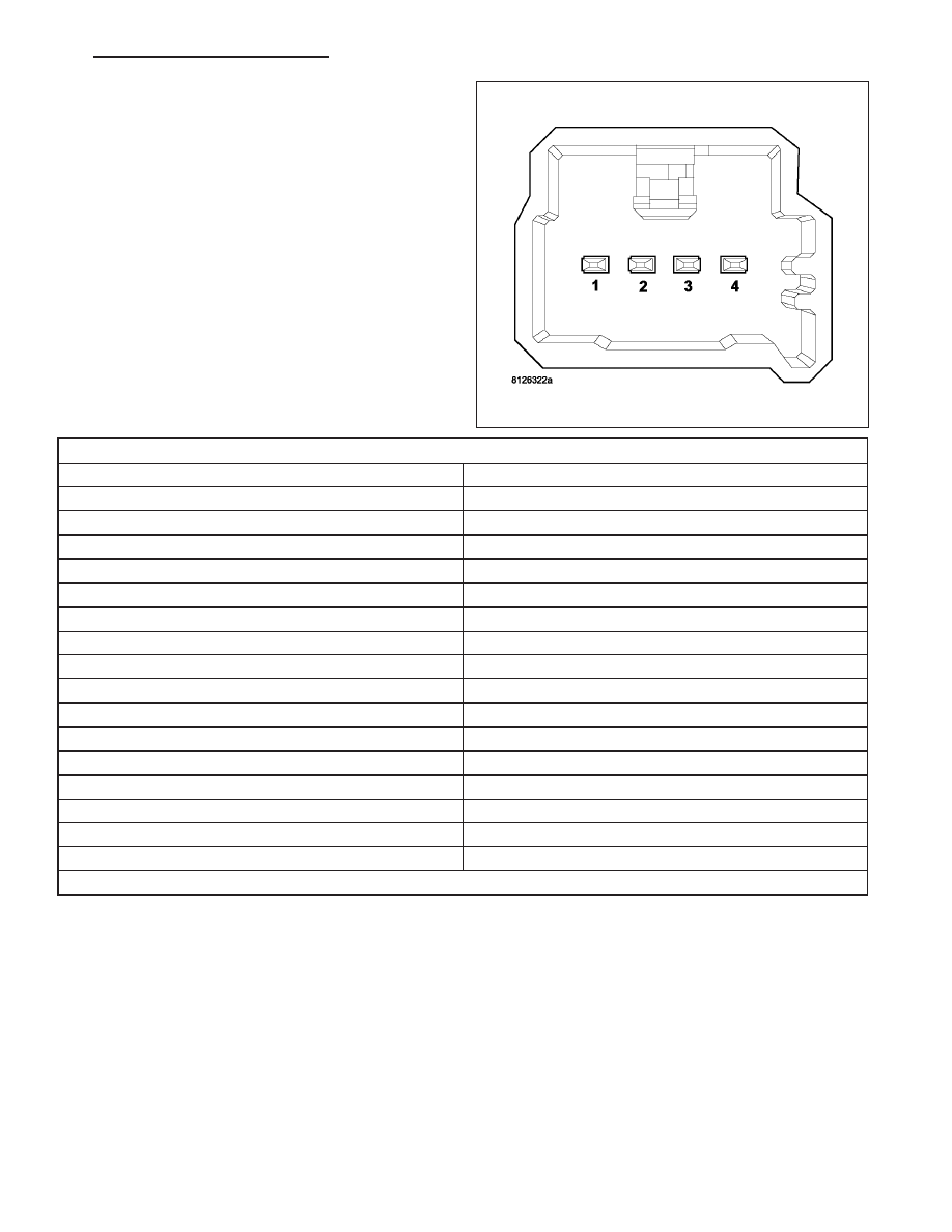
2. Disconnect the wire harness connector from the

back of the multi-function switch.

3. Using an ohmmeter, test the resistance between

the terminals of the switch as shown in the Multi-
Function Switch Tests table.

MULTI-FUNCTION SWITCH TESTS

SWITCH POSITION (PINS)

*RESISTANCE RANGE (OHMS)

BEAM SELECT/WASHER NEUTRAL (1 & 2)

OPEN CIRCUIT

BEAM SELECT ON (1 & 2)

518 - 575

OPTICAL HORN ON (1 & 2)

1257 - 1397

FRONT WASHER ON (1 & 2)

2584 - 2871

TURN/HAZARD OFF (2 & 3)

2643 - 2937

HAZARD ON (2 & 3)

115 - 128

LEFT TURN SIGNAL ON (2 & 3)

345 - 384

RIGHT TURN SIGNAL ON (2 & 3)

786 - 873

FRONT WIPER OFF (2 & 4)

6910 - 7678

FRONT WIPER DELAY 1 (2 & 4)

2128 - 2365

FRONT WIPER DELAY 2 (2 & 4)

1089 - 1210

FRONT WIPER DELAY 3 (2 & 4)

627 - 697

FRONT WIPER DELAY 4 (2 & 4)

388 - 431

FRONT WIPER DELAY 5 (2 & 4)

234 - 261

FRONT WIPER LOW (2 & 4)

125 - 140

FRONT WIPER HIGH (2 & 4)

50 - 56

* All Resistance Values Given Are ±10 Percent

4. If the switch fails any of the tests, replace the faulty multi-function switch as required.

REMOVAL

WARNING: To avoid personal injury or death, on vehicles equipped with airbags, disable the supplemental
restraint system before attempting any steering wheel, steering column, airbag, occupant classification sys-
tem, seat belt tensioner, impact sensor, or instrument panel component diagnosis or service. Disconnect
and isolate the battery negative (ground) cable, then wait two minutes for the system capacitor to discharge
before performing further diagnosis or service. This is the only sure way to disable the supplemental
restraint system. Failure to take the proper precautions could result in accidental airbag deployment.

HB

LAMPS/LIGHTING - EXTERIOR - SERVICE INFORMATION

8L - 111

1. Disconnect and isolate the battery negative cable.

2. Remove the driver airbag from the steering wheel.

(Refer to 8 - ELECTRICAL/RESTRAINTS/DRIVER
AIRBAG - REMOVAL).

3. Disconnect the steering wheel wire harness con-

nectors from the upper clockspring connector
receptacles.

CAUTION: Be certain that the screws that secure
the steering wheel puller to the steering wheel are
fully engaged in the steering wheel armature with-
out passing through the steering wheel and dam-
aging the clockspring.

4. Remove the steering wheel (1) from the steering

column.

(Refer

to

19

-

STEERING/COLUMN/

STEERING WHEEL - REMOVAL).

5. Grasp the tilt steering column knob (3) firmly and pull it straight rearward to remove it from the tilt adjuster lever

on the left side of the column.

6. From below the steering column, remove the two

outboard screws that secure the upper column
shroud (1) to the lower shroud (3).

7. Using hand pressure, press inward on both sides

of the upper shroud above the parting line of the
lower shroud to release the snap features that
secure the two shroud halves to each other.

8. Remove the upper shroud from the lower shroud

and the steering column.

9. Remove the one center screw that secures the

lower shroud to the steering column (4).

10. Remove the lower shroud from the steering

column.

11. Disconnect the wire harness connector (2) from

the back of the multi-function switch housing (1).

12. Remove the two screws (4) that secure the switch

to the multi-function switch mounting housing (3).

13. Grasp the switch control stalk and pull it toward

the left side of the vehicle to remove the switch
from the mounting housing.

8L - 112

LAMPS/LIGHTING - EXTERIOR - SERVICE INFORMATION

HB

INSTALLATION

WARNING: To avoid personal injury or death, on vehicles equipped with airbags, disable the supplemental
restraint system before attempting any steering wheel, steering column, airbag, occupant classification sys-
tem, seat belt tensioner, impact sensor, or instrument panel component diagnosis or service. Disconnect
and isolate the battery negative (ground) cable, then wait two minutes for the system capacitor to discharge
before performing further diagnosis or service. This is the only sure way to disable the supplemental
restraint system. Failure to take the proper precautions could result in accidental airbag deployment.

1. Slide the multi-function switch (1) into the multi-

function switch mounting housing (3) from the left
side. Be certain that the alignment pins on the top
and bottom of the switch are properly engaged in
the channels of the mounting housing.

2. Install and tighten the two screws (4) that secure

the switch to the mounting housing. Tighten the
screws to 2 N·m (20 in. lbs.).

3. Reconnect the wire harness connector (2) to the

back of the switch.

4. Position the lower shroud (3) onto the steering col-

umn (4).

5. From below the steering column, install and tighten

the one center screw that secures the lower shroud
to the steering column. Tighten the screw to 2 N·m
(20 in. lbs.).

6. Position the upper shroud (1) onto the steering col-

umn over the lower shroud. Be certain to engage
the gearshift lever gap hider into the opening in the
right side of both shroud halves.

7. Align the snap features on the upper shroud with

the receptacles in the lower shroud and apply hand
pressure to snap them together.

8. Install and tighten the two outboard screws that

secure the upper shroud to the lower shroud.
Tighten the screws to 2 N·m (20 in. lbs.).

HB

LAMPS/LIGHTING - EXTERIOR - SERVICE INFORMATION

8L - 113

9. Align the tilt steering column knob (3) with the tilt

adjuster lever on the left side of the steering col-
umn and use hand pressure to snap it back into
place.

NOTE: When reinstalling the steering wheel, be
certain to index the yellow rubber booted engage-
ment dowel on the upper surface of the clock-
spring rotor between the two fins cast into the
lower surface of the steering wheel armature hub.

10. Reinstall the steering wheel (1) onto the steering

column. (Refer to 19 - STEERING/COLUMN/
STEERING WHEEL - INSTALLATION).

11. Reconnect the steering wheel wire harness con-

nectors to the upper clockspring connector recep-
tacles. Be certain that the steering wheel wire harness is routed between the steering wheel back trim cover
and the steering wheel armature.

12. Reinstall the driver airbag onto the steering wheel. (Refer to 8 - ELECTRICAL/RESTRAINTS/DRIVER AIRBAG

- INSTALLATION).

13. Reconnect the battery negative cable.

SWITCH-PARKING BRAKE

DESCRIPTION

The park brake switch (1) is located on the park brake
lever mechanism on the cowl side inner panel below
the instrument panel, to the left of the steering col-
umn. This switch includes a spade-type output termi-
nal (3) that connects the switch to the vehicle
electrical system through a dedicated take out and
connector of the body wire harness. The output termi-
nal is integral to the stationary contact within a molded
plastic insulator.

A locating tab on the insulator engages a slot in the park brake lever mechanism for positive switch location. Exter-
nal to the insulator is a movable leaf contact with an integral grounding lug (4) on one end and an integral actuating
lever and follower (2) on the opposite end. The switch is secured to and grounded by a single screw to the park
brake lever mechanism. The park brake switch cannot be adjusted or repaired and, if faulty or damaged, it must be
replaced.

OPERATION

The park brake switch is a normally closed, mechanically actuated leaf contact switch that is operated by the park
brake lever mechanism. The switch is grounded through its mounting to the park brake lever mechanism and pro-

8L - 114

LAMPS/LIGHTING - EXTERIOR - SERVICE INFORMATION

HB


Content   ..  346  347  348  349   ..