Dodge Durango (HB). Manual - part 256


  Index      Dodge     Dodge Durango (HB) - service repair manual 2005 year


Search            


Content   ..  254  255  256  257   ..


Dodge Durango (HB). Manual - part 256


TESTING

VOLTAGE DROP TEST

WARNING: IF THE BATTERY SHOWS SIGNS OF FREEZING, LEAKING, LOOSE POSTS, OR LOW ELECTRO-
LYTE LEVEL, DO NOT TEST, ASSIST-BOOST, OR CHARGE. THE BATTERY MAY ARC INTERNALLY AND
EXPLODE. PERSONAL INJURY AND/OR VEHICLE DAMAGE MAY RESULT.

WARNING: EXPLOSIVE HYDROGEN GAS FORMS IN AND AROUND THE BATTERY. DO NOT SMOKE, USE
FLAME, OR CREATE SPARKS NEAR THE BATTERY. PERSONAL INJURY AND/OR VEHICLE DAMAGE MAY
RESULT.

WARNING: THE BATTERY CONTAINS SULFURIC ACID, WHICH IS POISONOUS AND CAUSTIC. AVOID CON-
TACT WITH THE SKIN, EYES, OR CLOTHING. IN THE EVENT OF CONTACT, FLUSH WITH WATER AND CALL
A PHYSICIAN IMMEDIATELY. KEEP OUT OF THE REACH OF CHILDREN.

WARNING: IF THE BATTERY IS EQUIPPED WITH REMOVABLE CELL CAPS, BE CERTAIN THAT EACH OF
THE CELL CAPS IS IN PLACE AND TIGHT BEFORE THE BATTERY IS RETURNED TO SERVICE. PERSONAL
INJURY AND/OR VEHICLE DAMAGE MAY RESULT FROM LOOSE OR MISSING CELL CAPS.

The following operation will require a voltmeter accurate to 1/10 (0.10) volt. Before performing this test, be certain
that the following procedures are accomplished:

The battery is fully-charged and tested.

Fully engage the parking brake.

If the vehicle is equipped with an automatic transmission, place the gearshift selector lever in the Park posi-
tion. If the vehicle is equipped with a manual transmission, place the gearshift selector lever in the Neutral
position and block the clutch pedal in the fully depressed position.

Verify that all lamps and accessories are turned off.

To prevent the engine from starting, remove the proper fuse in the PDC.

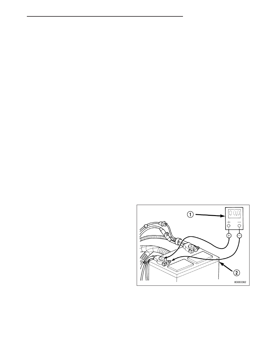
1. Connect the positive lead of the voltmeter (1) to

the battery negative terminal post. Connect the
negative lead of the voltmeter (1) to the battery
negative cable terminal clamp. Rotate and hold the
ignition switch in the Start position. Observe the
voltmeter. If voltage is detected, correct the poor
connection between the battery negative cable ter-
minal clamp and the battery negative terminal post.

HB

BATTERY SYSTEM

8F - 21

2. Connect the positive lead of the voltmeter (1) to the

battery positive terminal post. Connect the negative
lead of the voltmeter to the battery positive cable
terminal clamp. Rotate and hold the ignition switch
in the Start position. Observe the voltmeter. If volt-
age is detected, correct the poor connection
between the battery positive cable terminal clamp
and the battery positive terminal post.

3. Connect the voltmeter (2) to measure between the

battery positive cable terminal clamp (1) and the
starter solenoid (3) B(+) terminal stud. Rotate and
hold the ignition switch in the Start position.
Observe the voltmeter. If the reading is above 0.2
volt, clean and tighten the battery positive cable
eyelet terminal connection at the starter solenoid
B(+) terminal stud. Repeat the test. If the reading is
still above 0.2 volt, replace the faulty battery posi-
tive cable.

4. Connect the voltmeter (1) to measure between the

battery (2) negative cable terminal clamp and a
good clean ground (3) on the engine block. Rotate
and hold the ignition switch in the Start position.
Observe the voltmeter. If the reading is above 0.2
volt, clean and tighten the battery negative cable
eyelet terminal connection to the engine block.
Repeat the test. If the reading is still above 0.2 volt,
replace the faulty battery negative cable.

8F - 22

BATTERY SYSTEM

HB

THERMAL GUARD - BATTERY

DESCRIPTION

A flexible plastic bubble-wrap style thermal guard
wraps around the battery case to enclose the sides of
the battery. The thermal guard (1) consists of a heavy
black plastic outer skin and two lighter plies of plastic
that have been formed into a sheet with hundreds of
small air pockets entrapped between them.

OPERATION

The thermal guard protects the battery from engine compartment temperature extremes. The temperature of the
battery can affect battery performance. The air trapped between the plastic plies of the thermal guard create a dead
air space, which helps to insulate the sides of the battery case from the air temperature found in the surrounding
engine compartment.

HB

BATTERY SYSTEM

8F - 23

BATTERY TRAY

REMOVAL

1. Disconnect the battery cables.

2. Remove the battery thermal guard (1).

3. Remove the battery hold down (2) and bolt (1).

8F - 24

BATTERY SYSTEM

HB


Content   ..  254  255  256  257   ..