Dodge Durango (HB). Manual - part 244


  Index      Dodge     Dodge Durango (HB) - service repair manual 2005 year


Search            


Content   ..  242  243  244  245   ..


Dodge Durango (HB). Manual - part 244


BODY VERIFICATION TEST – VER 1

Diagnostic Test

1.

Perform Body Verification Test

Disconnect all jumper wires and reconnect all previously disconnected components and connectors.

Ensure that all accessories are turned off.

Ensure that the battery is fully charged.

Turn the ignition on.

With the scan tool, record and erase DTCs from all modules.

If an electronic control module was replaced, select the applicable module from the scan tool menu and press “Misc.
Functions”. If the module has programable features, program as necessary.

If repairs were made to any of the HVAC door actuator circuits, with the scan tool in HVAC, select System Tests and
then select Actuator DTC Detection. The test must pass before proceeding to the next step.

If repairs were made to any of the HVAC doors, linkage, door actuators, or door actuator circuits, with the scan tool
in HVAC, select System Tests and then select Actuator Calibration Test. The test must pass before proceeding to
the next step.

Turn the ignition off, wait 10 seconds, and then turn the ignition on.

Operate all functions of the system that caused the original concern.

With the scan tool, select ECU View.

Check for DTCs in the modules.

Are DTCs present in any of the modules or is the original condition still present?

Yes

>> The repair is not complete. Refer to the related category for the DTC or symptom that is still present.

No

>> The repair is complete.
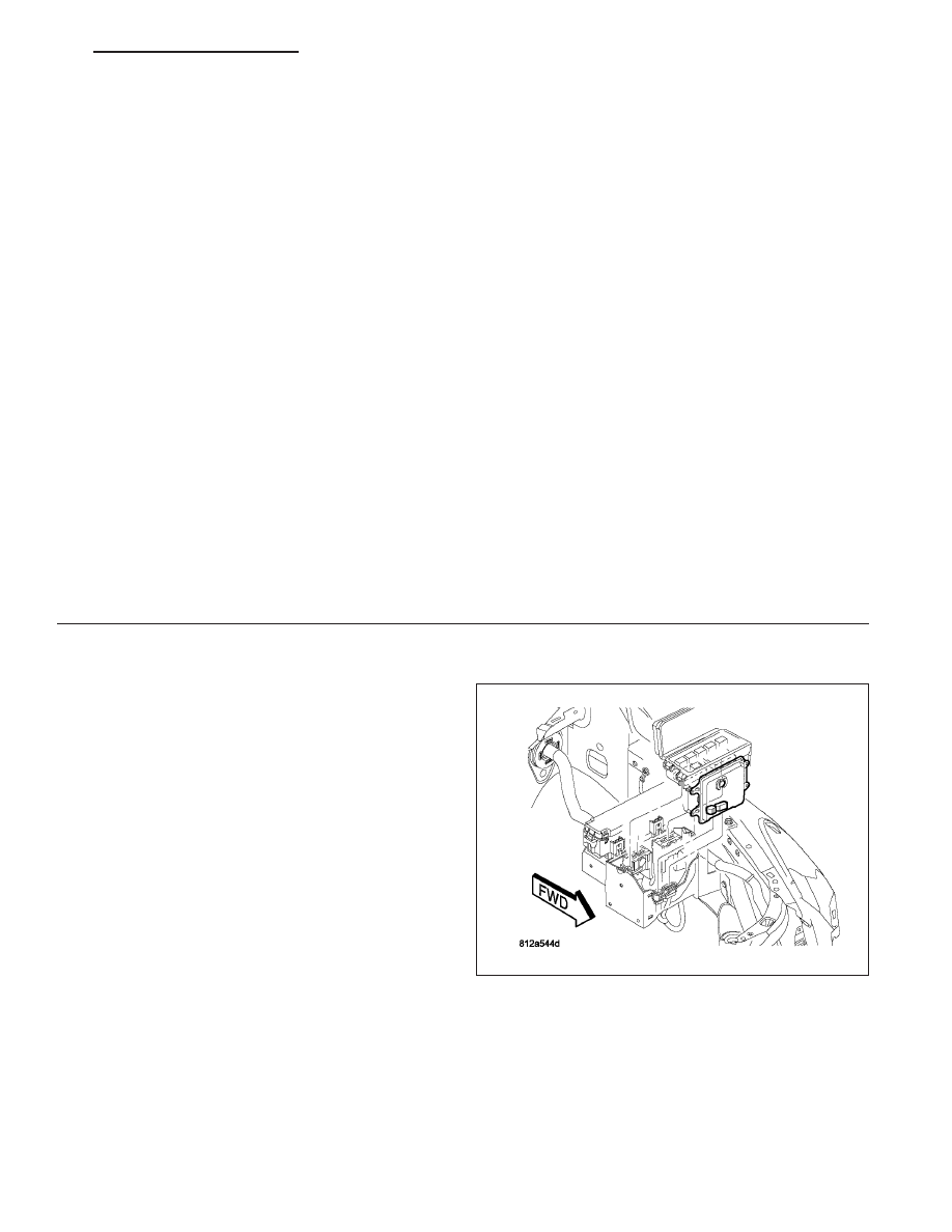
REMOVAL

1. Disconnect the positive and negative battery cables

from the battery.

2. Partially remove the Integrated Power Module

(IPM) from the engine compartment.

3. Remove the front control module retaining screws.

4. Pull the front control module straight from the IPM.

HB

ELECTRONIC CONTROL MODULES - SERVICE INFORMATION

8E - 197

INSTALLATION

1. Press the Front Control Module (FCM) onto the

Integrated Power Module (IPM).

2. Install the mounting fasteners.

3. Install the IPM.

4. Connect the positive and negative battery cables.

MODULE-MEMORY MIRROR

DESCRIPTION

There are two Memory Mirror Modules (these are
sometimes referred to as Driver Door Modules (DDM)
and Passenger Door Modules (PDM) within the mem-
ory system. One located in the driver door and one in
the passenger door, just behind the door trim panel.
The modules send a bus message to the power mir-
rors to adjust them to a preset position when a mem-
ory recall request has been made.

The memory mirror modules also act as an interface
in each door for electrical functions (door lock
switches and door ajar switches).

The Memory System makes available for immediate
recall personalized preferences of the following:

Automatic temperature control settings.

Outside mirror positions.

Power adjustable brake and accelerator pedal
position.

Power seat horizontal, vertical, recliner, and easy
entry positions.

Radio push button station selections.

The major components of the Memory System are:

Memory Selector Switch - located in the driver door trim panel.

Driver Memory Mirror Module (DMMM) - located in the driver door, behind the trim panel.

Passenger Memory Mirror Module (PMMM) - located in the passenger door, behind the trim panel.

Sentry Key Remote Entry Module (SKREEM) - located at ignition key cylinder.

Remote Keyless Entry (RKE) Transmitter - located with ignition key.

Memory Seat Module (MSM) - located underneath the driver seat and also controls the Adjustable Pedals.

Radio - located in the instrument panel center stack.

Automatic Temperature Control (ATC) - located in the instrument panel center stack.

8E - 198

ELECTRONIC CONTROL MODULES - SERVICE INFORMATION

HB

The memory recall is available at the press of a button on the drivers door trim panel or, by using the Remote
Keyless Entry (RKE) transmitter if it is programmed to trigger the recall.

Radio settings include up to 20 push button presets (10 AM and 10 FM), and the last station selection, even if it is
not one of the 20 preset selections.

OPERATION

The memory mirror module receives input from the door lock switches and sends that message to the cluster for
door lock operation (vehicles equipped with memory system only). It also controls the mirror adjustment by receiving
input from the mirror switch on the door trim panel. Sensors in the mirrors act as inputs to the memory mirror mod-
ule in order to position the mirrors to presets by the driver(s). The power supply to the mirrors is supplied by the
mirror memory modules. On vehicles equipped with a memory system, the front door ajar switches are inputs to the
memory mirror module. The modules use this information for door lock inhibit etc.

A memory setting is saved by pressing the “set” button, then pressing either the memory “1” or “2” button within 5
seconds of pressing the “set” button.

A memory setting is recalled by pressing either the memory “1” or “2” button, or by pressing the unlock button on
a “linked” Remote Keyless Entry (RKE) transmitter.

For driver safety, memorized settings can not be recalled if the transmission is in a position other than Park or the
seat belt is latched.

Both driver and passenger modules provide active and stored Diagnostic Trouble Codes (DTC’s) to aid in diagnosis.

Both modules are identical in appearance with the exception of an extra ground wire on the driver side memory
mirror module.

DIAGNOSIS AND TESTING

MEMORY MIRROR MODULE

Any diagnosis of the memory mirror module should begin with the use of a scan tool and the appropriate
Diagnostic information.

Refer to the appropriate wiring information.

REMOVAL

1. Disconnect and isolate the battery negative cable.

2. Remove the door trim panel (Refer to 23 - BODY/

DOOR - FRONT/TRIM PANEL - REMOVAL).

3. Disconnect the electrical connector (3) from module

(1).

4. Remove fasteners (2) and module (1) from vehicle.

HB

ELECTRONIC CONTROL MODULES - SERVICE INFORMATION

8E - 199

INSTALLATION

1. Position module (1) on door and install fasteners

(2).

2. Connect the electrical connector (3) to module (1).

3. Install the door trim panel (Refer to 23 - BODY/

DOOR - FRONT/TRIM PANEL - INSTALLATION).

4. Connect the battery negative cable.

5. Verify system and vehicle operation.

MODULE-SEAT MEMORY

DESCRIPTION

The Memory Seat Module (MSM) is located under-
neath the driver seat, towards the front and on the
outboard side. It is used in conjunction with the other
modules in the memory system (Refer to 8 - ELEC-
TRICAL/ELECTRONIC CONTROL MODULES/MEM-
ORY

HEATED

SEAT/MIRROR

MODULE

-

DESCRIPTION) to recall the seat to one of two preset
seat functional adjustments (horizontal, vertical, and
recliner). The switch for the memory seat program-
ming and selection mounts on the driver door trim
panel. The MSM also controls the adjustable pedals,
both for the memory and manual functionality. The
adjustable accelerator and brake pedals are available
on SLT and Limited models. On Limited, their position-
ing can be stored for recall by the memory system,
allowing for two drivers to have unique, pre-pro-
grammed settings.

OPERATION

POWER/MEMORY SEAT

The memory seat module receives input from the 8-way power seat switch, the driver seat position sensors, adjust-
able pedal control circuits (switch, sensor, and motor), and the data bus circuit. The memory switch, is wired to the
memory mirror module which sends the message over the data bus.

The memory seat module performs the following functions:

Positions the driver seat (vertical, horizontal, and recliner positions) and adjustable pedals.

Sends the memory save or recall (#1 or #2) command over the data bus circuit to the memory mirror modules,
HVAC, and radio.

Provides for “linking” the key FOBs to memory.

8E - 200

ELECTRONIC CONTROL MODULES - SERVICE INFORMATION

HB


Content   ..  242  243  244  245   ..