Content .. 1576 1577 1578 1579 ..
Dodge Durango (HB). Manual - part 1578
evaporative system. The diaphragm actuates the switch. This is above the opening point of the fuel inlet check
valve in the fill tube so cap off leaks can be detected. Submerged fill systems must have recirculation lines that do
not have the in-line normally closed check valve that protects the system from failed nozzle liquid ingestion, in order
to detect cap off conditions.
The normally closed valve in the NVLD is intended to maintain the seal on the evaporative system during the
engine off condition. If vacuum in the evaporative system exceeds 3
9
to 6
9
H2O (0.75 to 1.5 KPA), the valve will be
pulled off the seat, opening the seal. This will protect the system from excessive vacuum as well as allowing suf-
ficient purge flow in the event that the solenoid was to become inoperative.
The solenoid actuates the valve to unseal the canister vent while the engine is running. It also will be used to close
the vent during the medium and large leak tests and during the purge flow check. This solenoid requires an initial
1.5 amps of current to pull the valve open, but after 100 mili-seconds, will be duty cycled down to an average of
about 150 mA for the remainder of the drive cycle.
Another feature in the device is a diaphragm that will open the seal in the NVLD with pressure in the evaporative
system. The device will
9
blow off
9
at about 0.5
9
H2O (0.12 KPA) pressure to permit the venting of vapors during
refueling. An added benefit to this is that it will also allow the tank to
9
breathe
9
during increasing temperatures, thus
limiting the pressure in the tank to this low level. This is beneficial because the induced vacuum during a subse-
quent declining temperature will achieve the switch closed (pass threshold) sooner than if the tank had to decay
from a built up pressure.
The device itself has 3 wires: Switch sense, solenoid driver and ground. It also includes a resistor to protect the
switch from a short to battery or a short to ground. The NGC utilizes a high-side driver to energize and duty-cycle
the solenoid.
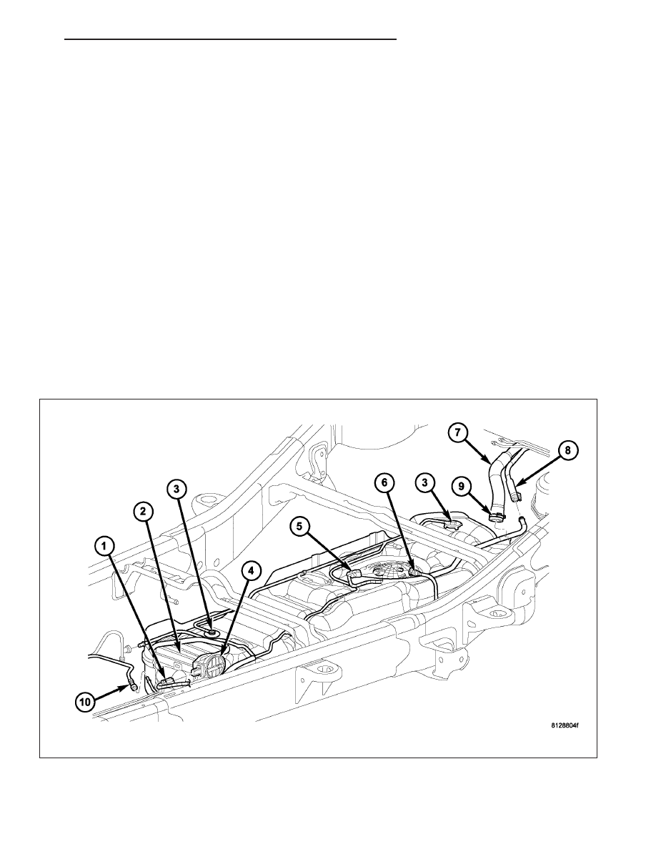
REMOVAL
The NVLD pump (4) is located at the front of the fuel
tank.
1. Raise and support vehicle.
HB
EVAPORATIVE EMISSIONS
25 - 15