Dodge Durango (HB). Manual - part 1559


  Index      Dodge     Dodge Durango (HB) - service repair manual 2005 year


Search            


Content   ..  1557  1558  1559  1560   ..


Dodge Durango (HB). Manual - part 1559


REFRIGERANT SYSTEM RECOVERY

WARNING: Refer to the applicable warnings and cautions for this system before performing the following
operation (Refer to 24 - HEATING & AIR CONDITIONING/PLUMBING - FRONT - WARNINGS) and (Refer to 24
- HEATING & AIR CONDITIONING/PLUMBING - FRONT - CAUTIONS). Failure to follow the warnings and cau-
tions could result in possible personal injury or death.

NOTE: If equipped with the rear heating-A/C sys-
tem, use a heat gun to heat the underbody lines to
help remove any trapped refrigerant from the rear
A/C system.

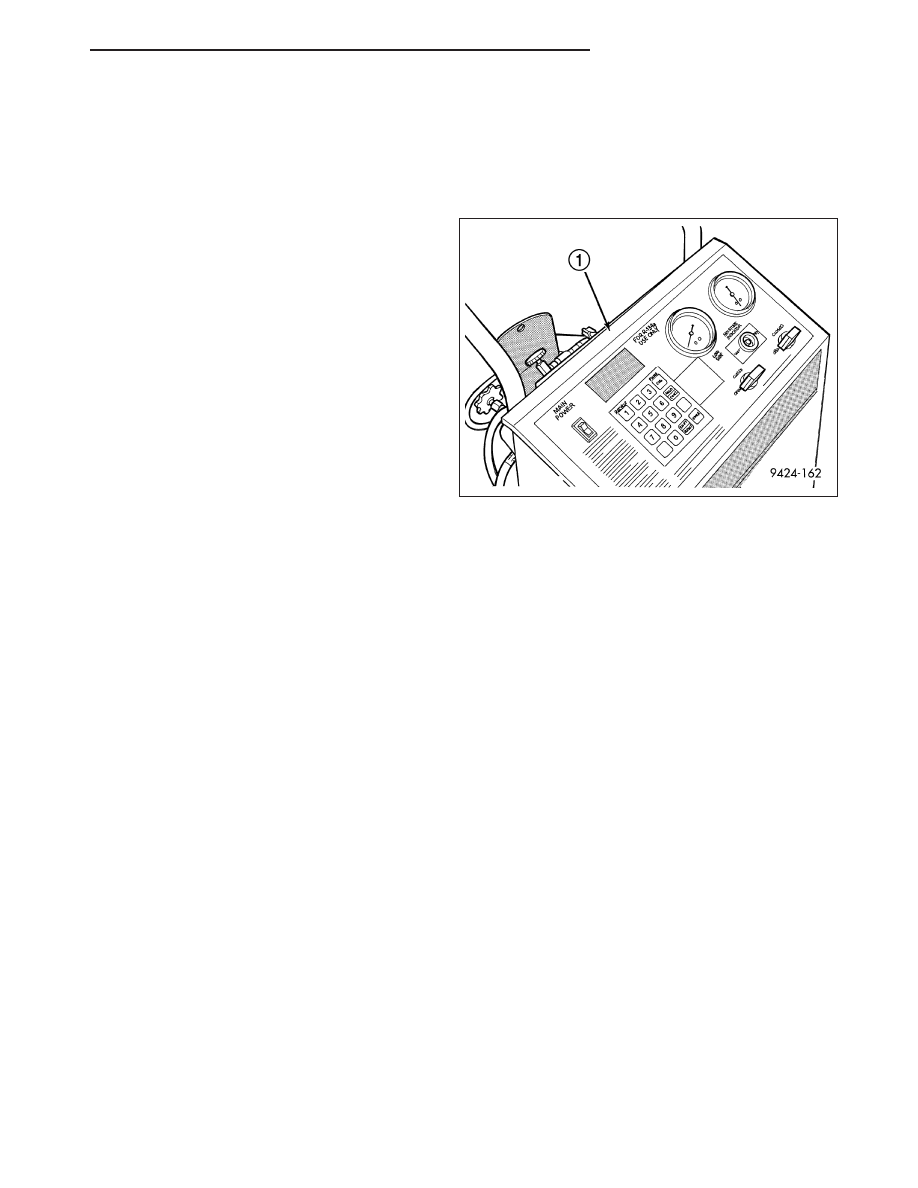
An R-134a refrigerant recovery/recycling/charging sta-
tion (1) that meets SAE standard J2210 must be used
to recover the refrigerant from the R-134a refrigerant
system. Refer to the operating instructions supplied by
the equipment manufacturer for the proper care and
use of this equipment.

REFRIGERANT SYSTEM EVACUATE

NOTE: Special effort must be used to prevent moisture from entering the A/C system oil. Moisture in the oil
is very difficult to remove and will cause a reliability problem with the compressor.

If a compressor designed to use R-134a refrigerant is left open to the atmosphere for an extended period of time.
It is recommended that the refrigerant oil be drained and replaced with new oil or a new A/C compressor be used.
This will eliminate the possibility of contaminating the refrigerant system.

If the refrigerant system has been open to the atmosphere, it must be evacuated before the system can be filled.
Moisture and air mixed with the refrigerant will raise the compressor head pressure above acceptable operating
levels. This will reduce the performance of the A/C system and damage the A/C compressor. Moisture will boil at
near room temperature when exposed to vacuum. To evacuate the refrigerant system:

NOTE: When connecting the service equipment coupling to the line fitting, verify that the valve of the cou-
pling is fully closed. This will reduce the amount of effort required to make the connection.

1. Recover the refrigerant system (Refer to 24 - HEATING & AIR CONDITIONING/PLUMBING - FRONT - STAN-

DARD PROCEDURE - REFRIGERANT SYSTEM RECOVERY).

2. Connect a suitable charging station, refrigerant recovery machine or a manifold gauge set with vacuum pump

and refrigerant recovery equipment (Refer to 24 - HEATING & AIR CONDITIONING/PLUMBING - FRONT -
STANDARD PROCEDURE - REFRIGERANT SYSTEM SERVICE EQUIPMENT).

3. Open the suction and discharge valves and start the vacuum pump. The vacuum pump should run a minimum of

45 minutes prior to charge to eliminate all moisture in system. When the suction gauge reads -88 kPa (- 26 in.
Hg) vacuum or greater for 30 minutes, close all valves and turn off vacuum pump. If the system fails to reach
specified vacuum, the refrigerant system likely has a leak that must be corrected. If the refrigerant system main-
tains specified vacuum for at least 30 minutes, start the vacuum pump, open the suction and discharge valves.
Then allow the system to evacuate an additional 10 minutes.

4. Close all valves. Turn off and disconnect the vacuum pump.

5. Charge the refrigerant system (Refer to 24 - HEATING & AIR CONDITIONING/PLUMBING - FRONT - STAN-

DARD PROCEDURE - REFRIGERANT SYSTEM CHARGE).

HB

PLUMBING - FRONT

24 - 429

REFRIGERANT SYSTEM CHARGE

WARNING: Refer to the applicable warnings and cautions for this system before performing the following
operation (Refer to 24 - HEATING & AIR CONDITIONING/PLUMBING - FRONT - WARNINGS) and (Refer to 24
- HEATING & AIR CONDITIONING/PLUMBING - FRONT - CAUTIONS). Failure to follow the warnings and cau-
tions could result in possible personal injury or death.

NOTE: Always refer to the underhood HVAC Specification Label for the refrigerant fill specification of the
vehicle being serviced.

After all refrigerant system leaks have been repaired and the refrigerant system has been evacuated, a refrigerant
charge can be injected into the system. For the proper amount of the refrigerant charge, refer to the underhood
HVAC Specification Label.

A R-134a refrigerant recovery/recycling/charging station that meets SAE Standard J2210 must be used to charge
the refrigerant system with R-134a refrigerant. Refer to the operating instructions supplied by the equipment man-
ufacturer for proper care and use of this equipment.

CHARGING PROCEDURE

CAUTION: A small amount of refrigerant oil is removed from the A/C system each time the refrigerant sys-
tem is recovered and evacuated. Before charging the A/C system, you MUST replenish any oil lost during
the recovery process. Refer the equipment manufacturer instructions for more information.

1. Evacuate the refrigerant system (Refer to 24 - HEATING & AIR CONDITIONING/PLUMBING - FRONT - STAN-

DARD PROCEDURE - REFRIGERANT SYSTEM EVACUATE).

2. A manifold gauge set and an R-134a refrigerant recovery/recycling/charging station that meets SAE standard

J2210 should be connected to the refrigerant system.

3. Measure the proper amount of refrigerant and heat it to 52° C (125° F) with the charging station. See the oper-

ating instructions supplied by the equipment manufacturer for proper use of this equipment.

4. Open both the suction and discharge valves, then open the charge valve to allow the heated refrigerant to flow

into the system.

5. When the transfer of refrigerant has stopped, close both the suction and discharge valves.

6. If all of the refrigerant charge did not transfer from the dispensing device, open all of the windows in the vehicle

and set the heating-A/C system controls so that the A/C compressor is engaged and the blower motor is oper-
ating at its lowest speed setting. Run the engine at a steady high idle (about 1400 rpm). If the A/C compressor
does not engage, test the compressor clutch control circuit and repair as required.

7. Open the low-side valve to allow the remaining refrigerant to transfer to the refrigerant system.

WARNING: Take care not to open the discharge (high pressure) valve at this time. Failure to follow this
warning could result in possible personal injury or death.

8. Disconnect the charging station and manifold gauge set from the refrigerant system service ports.

9. Reinstall the caps onto the refrigerant system service ports.

24 - 430

PLUMBING - FRONT

HB

COMPRESSOR-A/C

DESCRIPTION

A/C COMPRESSOR

The A/C system uses a Denso 10S20, five double-act-
ing piston, reciprocating swash plate-type A/C com-
pressor (1) on all models. This A/C compressor has a
fixed displacement of 200 cubic centimeters (12.2
cubic inches) and has both the suction and discharge
ports (2) located at the rear of the compressor on the
cylinder head (3).

A label identifying the use of R-134a refrigerant is
located on the A/C compressor.

HIGH PRESSURE RELIEF VALVE

A high pressure relief valve is located on the compressor cylinder head, which is at the rear of the A/C compressor.
This mechanical valve is designed to vent refrigerant from the A/C system to protect against damage to the A/C
compressor and other A/C system components, caused by condenser air flow restriction or an overcharge of
refrigerant.

OPERATION

A/C COMPRESSOR

The A/C compressor is driven by the engine through an electric clutch, drive pulley and belt arrangement. The A/C
compressor is lubricated by refrigerant oil that is circulated throughout the refrigerant system with the refrigerant.

The A/C compressor draws in low-pressure refrigerant vapor from the A/C evaporator through its suction port. It then
compresses the refrigerant into a high-pressure, high-temperature refrigerant vapor, which is then pumped to the
A/C condenser through the compressor discharge port.

The A/C compressor cannot be repaired and, if faulty or damaged, it must be replaced. The compressor clutch,
pulley and bearing assembly, and clutch field coil are available for service.

HIGH PRESSURE RELIEF VALVE

The high pressure relief valve vents refrigerant from the A/C system when a discharge pressure of 3445 to 4135
kPa (500 to 600 psi) or above is reached. The high pressure relief valve closes with a minimum discharge pressure
of 2756 kPa (400 psi) is reached.

The high pressure relief valve vents only enough refrigerant to reduce the A/C system pressure, and then re-seats
itself. The majority of the refrigerant is conserved in the A/C system. If the high pressure relief valve vents refrig-
erant, it does not mean the valve is faulty.

The high pressure relief valve is factory-calibrated and cannot be adjusted or repaired, and must not be removed or
otherwise disturbed. The valve is only serviced as a part of the A/C compressor.

HB

PLUMBING - FRONT

24 - 431

DIAGNOSIS AND TESTING

A/C COMPRESSOR

When investigating an A/C system related noise, you must first know the conditions under which the noise occurs.
These conditions include: weather, vehicle speed, transmission in gear or neutral, engine speed, engine tempera-
ture, and any other special conditions. Noises that develop during A/C operation can often be misleading. For exam-
ple: What sounds like a failed front engine bearing or connecting rod, may be caused by loose bolts, nuts, mounting
brackets or a loose compressor clutch assembly.

Drive belts are speed sensitive. At different engine speeds and depending upon drive belt tension, drive belts can
develop noises that are mistaken for an A/C compressor noise. Improper drive belt tension can cause a misleading
noise when the compressor clutch is engaged, which may not occur when the compressor clutch is disengaged.
Check the accessory drive belt condition and tension as described in Cooling before beginning this procedure.

1. Select a quiet area for testing. Duplicate the complaint conditions as much as possible. Turn the A/C compressor

On and Off several times to clearly identify the compressor noise. Listen to the A/C compressor while the clutch
is engaged and disengaged. Probe the A/C compressor with an engine stethoscope or a long screwdriver with
the handle held to your ear to better localize the source of the noise.

2. Loosen all of the compressor mounting hardware and retighten. Check the compressor clutch retainer. Be certain

that the clutch field coil is mounted securely to the A/C compressor, and that the clutch plate and pulley are
properly aligned and have the correct air gap (Refer to 24 - HEATING & AIR CONDITIONING/CONTROLS -
FRONT/CLUTCH-A/C COMPRESSOR - INSTALLATION).

3. To duplicate high-ambient temperature conditions (high head pressure), restrict the air flow through the A/C con-

denser. Install a manifold gauge set or a scan tool to be certain that the discharge pressure does not exceed
2760 kPa (400 psi).

4. Check the refrigerant system plumbing for incorrect routing, rubbing or interference, which can cause unusual

noises. Also check the refrigerant lines and hoses for kinks or sharp bends that will restrict refrigerant flow, which
can cause noises (Refer to 24 - HEATING & AIR CONDITIONING/PLUMBING - FRONT - DESCRIPTION)

5. If the noise is from opening and closing of the high pressure relief valve, recover, evacuate and recharge the

refrigerant system (Refer to 24 - HEATING & AIR CONDITIONING/PLUMBING - FRONT - STANDARD PROCE-
DURE - REFRIGERANT SYSTEM RECOVERY), (Refer to 24 - HEATING & AIR CONDITIONING/PLUMBING -
FRONT - STANDARD PROCEDURE - REFRIGERANT SYSTEM EVACUATE) and (Refer to 24 - HEATING &
AIR CONDITIONING/PLUMBING - FRONT - STANDARD PROCEDURE - REFRIGERANT SYSTEM CHARGE).
If the high pressure relief valve still does not seat properly, replace the compressor (Refer to 24 - HEATING &
AIR CONDITIONING/PLUMBING - FRONT/COMPRESSOR-A/C - REMOVAL).

6. If the noise is from liquid refrigerant slugging on the suction line, replace the receiver/drier (Refer to 24 - HEAT-

ING & AIR CONDITIONING/PLUMBING - FRONT/RECEIVER / DRIER - REMOVAL) and check the refrigerant oil
level and the refrigerant system charge (Refer to 24 - HEATING & AIR CONDITIONING/PLUMBING - FRONT/
REFRIGERANT OIL - STANDARD PROCEDURE - REFRIGERANT OIL LEVEL) (Refer to 24 - HEATING & AIR
CONDITIONING/PLUMBING - FRONT - STANDARD PROCEDURE - REFRIGERANT SYSTEM CHARGE).

7. If a slugging condition still exists after replacing the receiver/drier, then replace the A/C compressor (Refer to 24

- HEATING & AIR CONDITIONING/PLUMBING - FRONT/COMPRESSOR-A/C - REMOVAL) and repeat Step 1.

REMOVAL

WARNING: Refer to the applicable warnings and cautions for this system before performing the following
operation (Refer to 24 - HEATING & AIR CONDITIONING/PLUMBING - FRONT - WARNINGS) and (Refer to 24
- HEATING & AIR CONDITIONING/PLUMBING - FRONT - CAUTIONS). Failure to follow the warnings and cau-
tions could result in possible personal injury or death.

NOTE: The A/C compressor may be removed and repositioned without disconnecting the refrigerant lines or
discharging the refrigerant system. Discharging is not necessary if servicing the compressor clutch, clutch
coil, engine, engine cylinder head or the generator.

24 - 432

PLUMBING - FRONT

HB


Content   ..  1557  1558  1559  1560   ..