Dodge Durango (HB). Manual - part 1528


  Index      Dodge     Dodge Durango (HB) - service repair manual 2005 year


Search            


Content   ..  1526  1527  1528  1529   ..


Dodge Durango (HB). Manual - part 1528


U0019–CAN B BUS (MTC) (CONTINUED)

3.

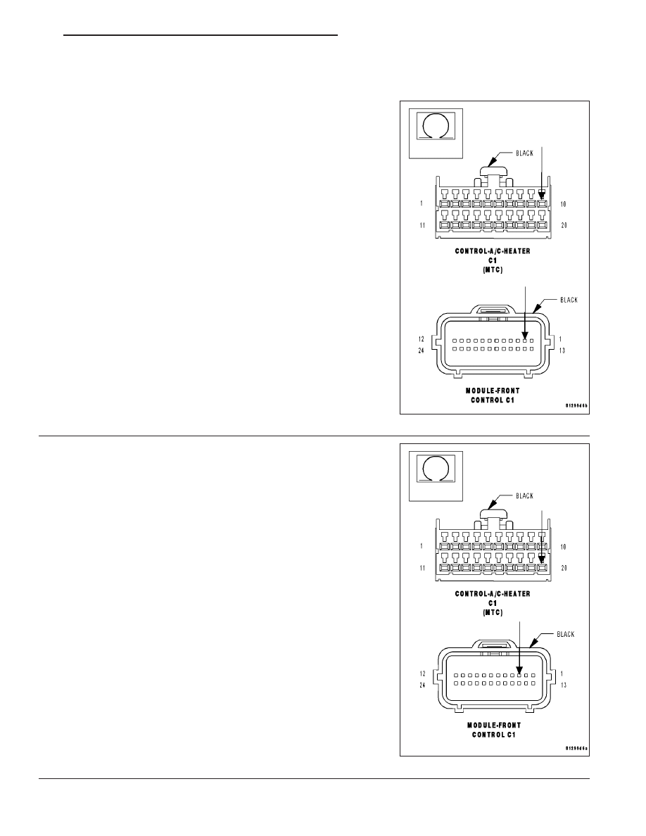
CHECK (D55) CAN B BUS (+) CIRCUIT FOR AN OPEN

Turn the ignition off.

Disconnect the negative battery cable.

Disconnect the A/C Heater Control C1 harness connector.

Disconnect the Front Control Module (FCM) C1 harness connector.

Measure the resistance of the (D55) CAN B Bus (+) circuit between
the Front Control Module C1 harness connector and the A/C Heater
Control C1 harness connector.

Is the resistance below 2.0 ohms?

Yes

>> Go To 4

No

>> Repair the (D55) CAN B Bus (+) circuit for an open.

Perform BODY VERIFICATION TEST - VER 1.

4.

CHECK (D54) CAN B BUS (–) CIRCUIT FOR AN OPEN

Measure the resistance of the (D54) CAN B Bus (–) circuit between
the Front Control Module C1 connector and the A/C Heater Control C1
harness connector.

Is the resistance below 2.0 ohms?

Yes

>> Replace the A/C Heater Control in accordance with the

Service Information.

Perform BODY VERIFICATION TEST - VER 1.

No

>> Repair the (D54) CAN B Bus (–) circuit for an open.

Perform BODY VERIFICATION TEST - VER 1.

HB

HVAC - ELECTRICAL DIAGNOSTICS

24 - 305

U0141–LOST COMMUNICATION WITH FRONT CONTROL MODULE (ATC & MTC)

For the Automatic or Manual Temperature Control (ATC or MTC) circuit diagram (Refer to 24 - HEATING & AIR
CONDITIONING - SCHEMATICS AND DIAGRAMS).

For a complete wiring diagram Refer to Section 8W.

When Monitored:
With the ignition on.

Set Condition:
If the A/C Heater Control looses communication with the Front Control Module (FCM). This DTC has a matur-
ing time of 30 seconds and a de-maturing time of 10 seconds. If the DTC’s status changes from active to
stored it will stay in memory for 100 ignition cycles.

(Refer to 8 - ELECTRICAL/ELECTRONIC CONTROL MODULES - DIAGNOSIS AND TESTING) for the diagnostic
test procedure.

24 - 306

HVAC - ELECTRICAL DIAGNOSTICS

HB

U0155–LOST COMMUNICATION WITH CLUSTER/CCN (ATC & MTC)

For the Automatic or Manual Temperature Control (ATC or MTC) circuit diagram (Refer to 24 - HEATING & AIR
CONDITIONING - SCHEMATICS AND DIAGRAMS).

For a complete wiring diagram Refer to Section 8W.

When Monitored:
With the ignition on.

Set Condition:
If the A/C Heater Control looses communication with the Cluster (CCN). This DTC has a maturing time of 30
seconds and a de-maturing time of 10 seconds. If the DTC’s status changes from active to stored it will stay
in memory for 100 ignition cycles.

(Refer to 8 - ELECTRICAL/ELECTRONIC CONTROL MODULES - DIAGNOSIS AND TESTING) for the diagnostic
test procedure.

HB

HVAC - ELECTRICAL DIAGNOSTICS

24 - 307

U0156–LOST COMMUNICATION WITH EOM (ATC)

For the Automatic Temperature Control (ATC) circuit diagram (Refer to 24 - HEATING & AIR CONDITIONING -
SCHEMATICS AND DIAGRAMS).

For a complete wiring diagram Refer to Section 8W.

When Monitored:
With the ignition on.

Set Condition:
If the A/C Heater Control looses communication with the Compass Temperature Module (EOM). This DTC has
a maturing time of 30 seconds and a de-maturing time of 10 seconds. If the DTC’s status changes from active
to stored it will stay in memory for 100 ignition cycles.

(Refer to 8 - ELECTRICAL/ELECTRONIC CONTROL MODULES - DIAGNOSIS AND TESTING) for the diagnostic
test procedure.

24 - 308

HVAC - ELECTRICAL DIAGNOSTICS

HB


Content   ..  1526  1527  1528  1529   ..