Content .. 1493 1494 1495 1496 ..
Dodge Durango (HB). Manual - part 1495
B1041–PANEL MODE DOOR 1 CONTROL CIRCUIT LOW (MTC) (CONTINUED)
2.
CHECK (C29) MODE DOOR 1 DRIVER CIRCUIT FOR A SHORT TO OTHER DOOR DRIVER CIRCUITS
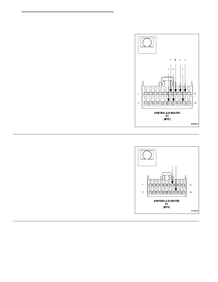
Measure the resistance between the (C29) Mode Door 1 Driver circuit
and the (C61) Front Blend Door Driver circuit, the (C801) Mode Door 2
Driver circuit, the (C32) Recirculation Door Driver circuit, and, if
equipped, the (C53) Rear Mode Door Driver circuit, the (C154) Rear
Common Door Driver circuit, and the (C54) Rear Blend Door Driver
circuit in the A/C Heater Control C1 harness connector.
Is the resistance below 10k ohms between the (C29) Mode Door
1 Driver circuit and any of the other door driver circuits?
Yes
>> Repair the circuit(s) with a resistance below 10k ohms for
a short to the (C29) Mode Door 1 Driver circuit.
Perform BODY VERIFICATION TEST - VER 1.
No
>> Go To 3
3.
CHECK MODE DOOR 1 (FLOOR TO PANEL) ACTUATOR CIRCUIT RESISTANCE
Measure the resistance between the (C29) Mode Door 1 Driver circuit
and the (C34) Front Common Door Driver circuit in the A/C Heater
Control C1 harness connector.
Is the resistance below 30 ohms?
Yes
>> Go To 4
No
>> Go To 5
HB
HVAC - ELECTRICAL DIAGNOSTICS
24 - 173