Dodge Durango (HB). Manual - part 1366


  Index      Dodge     Dodge Durango (HB) - service repair manual 2005 year


Search            


Content   ..  1364  1365  1366  1367   ..


Dodge Durango (HB). Manual - part 1366


SEAL-EXTENSION HOUSING

REMOVAL

1. Raise and support vehicle.

2. Remove rear propeller shaft. (Refer to 3 - DIFFERENTIAL & DRIVELINE/PROPELLER SHAFT/PROPELLER

SHAFT - REMOVAL)

3. Using a suitable pry tool or slide-hammer mounted screw, remove the extension housing seal.

INSTALLATION

1. Clean fluid residue from sealing surface and

inspect for defects.

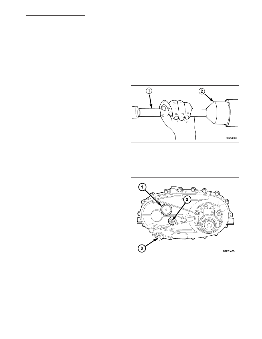
2. Using Installer D-163 (2) and Handle C-4171 (1),

install seal in extension housing.

3. Install propeller shaft. (Refer to 3 - DIFFERENTIAL

& DRIVELINE/PROPELLER SHAFT/PROPELLER
SHAFT - INSTALLATION)

4. Verify proper transfer case fluid level.

5. Lower vehicle.

FLUID

STANDARD PROCEDURE - FLUID DRAIN AND REFILL

NOTE: The fill (2) and drain (3) plugs are both in
the rear case.

1. Raise vehicle.

2. Position drain pan under transfer case.

3. Remove drain (3) and fill (2) plugs and drain lubri-

cant completely.

4. Install drain plug (3). Tighten plug to 20-34 N·m

(15-25 ft. lbs.).

5. Remove drain pan.

6. Fill transfer case to bottom edge of fill plug opening

with Mopar

T

ATF +4, Automatic Transmission fluid.

7. Install and tighten fill plug (2) to 20-34 N·m (15-25

ft. lbs.).

8. Lower vehicle.

HB

TRANSFER CASE - NV244 GENII - SERVICE INFORMATION

21 - 869

SEAL-FRONT OUTPUT SHAFT

REMOVAL

1. Remove the front propeller shaft (Refer to 3 - DIF-

FERENTIAL & DRIVELINE/PROPELLER SHAFT/
PROPELLER SHAFT - REMOVAL).

2. Remove the front propeller shaft seal boot retaining

clamp (2).

3. Remove the front propeller shaft seal boot (1) from

the front output shaft seal slinger.

4. Remove the front output shaft seal slinger (1) by

bending the slinger away (2) from the transfer
case.

5. Using a suitable pry tool, remove the slinger from

the output shaft using care not to damage the
shaft.

6. Using a screw and a slide hammer, remove the

front output shaft seal.

21 - 870

TRANSFER CASE - NV244 GENII - SERVICE INFORMATION

HB

INSTALLATION

1. Install the new front output shaft seal with Installer MB991168A.

2. Install the front output shaft seal slinger with Installer 8840. Install the slinger onto the shaft until the tool contacts

the rear of the output shaft.

3. Install a new seal boot clamp onto the seal boot.

4. Install the seal boot and clamp onto the slinger hub and tighten the clamp with Crimp Tool C-4975-A.

5. Install front propeller shaft (Refer to 3 - DIFFERENTIAL & DRIVELINE/PROPELLER SHAFT/PROPELLER

SHAFT - INSTALLATION).

SENSOR-MODE

DESCRIPTION

The transfer case mode sensor (1) provides the Front
Control Module (FCM) feedback about the position of
the transfer case. The sensor consists of a linear ana-
log position sensor that converts the motor output
shaft position into a DC signal. The sensor may rotate
a full 360 degrees for both the NV144 and the NV244
GENII. The operating envelope or sector rotation is -5
to 180 degrees for the NV144 and -40 to 20 degrees
for the NV244 GENII. The FCM must supply 5VDC
(+/- 0.5v) to the sensor whenever the FCM is not in
sleep mode and monitor the shift motor position. The
sensor position is monitored when the ignition is in the
RUN position and for 10 seconds after the ignition is
shifted to the OFF position. The sensor is mechani-
cally linked to the shaft of the cam which allows the
transfer case to shift. The mode sensor will draw less
than 20 mA of current during operation.

OPERATION

During normal vehicle operation, the Front Control Module (FCM) monitors the mode sensor outputs at least every
2 milliseconds when the shift motor is stationary or active.

Refer to SECTOR ANGLES vs. TRANSFER CASE POSITION for the relative angles of the transfer case shift sector
versus the interpreted transfer case gear operating mode.

SECTOR ANGLES vs. TRANSFER CASE POSITION

Shaft Angle (Degrees)

Transfer Case Position

+20

4LO

0

N

-20

AWD

-40

4LOCK

NOTE: All the parameter voltages referred to in the following information are calibrated items in the con-
troller software and are subject to change.

NOTE: For a further explanation of Phase 1 through 3 shifting, (Refer to 8 - ELECTRICAL/ELECTRONIC
CONTROL MODULES/TRANSFER CASE CONTROL MODULE - OPERATION).

HB

TRANSFER CASE - NV244 GENII - SERVICE INFORMATION

21 - 871

The following information describes the different mode sensor positions:

4LO TARGET REGION - The position shall be considered 4LO if the voltage is greater than or equal to
encoder_4LO_min Volts and it is also less than or equal to encoder_4LO_max Volts.

4LO SHIFT LIMIT - During Phase 2 and Phase 3 shifting, shifts may become unidirectional when a voltage is
less than or equal to encoder_4LO_min Volts has been reached.

4LOCK TARGET REGION - The position shall be considered 4LOCK if the voltage is greater than or equal to
encoder_4LOCK_min Volts and it is also less than or equal to encoder_4LOCK_max Volts.

NEUTRAL TARGET REGION - The position shall be considered NEUTRAL if the voltage is greater than or
equal to encoder_Neutral_min Volts and it is also less than or equal to encoder_Neutral_max Volts.

AWD TARGET REGION - The position shall be considered AWD if the voltage is greater than or equal to
encoder_AWD_min Volts and it is also less than or equal to encoder_AWD_max Volts.

AWD SHIFT LIMIT - During Phase 2 and Phase 3 shifting, shifts may become unidirectional when a voltage is
greater than or equal to encoder_AWD_min Volts has been reached.

The mode sensor position will be considered invalid by the FCM if the voltage is greater than or equal to encoder-
_High_Range_Limit Volts or if it is less than or equal to encoder_Low_Range_Limit Volts.

Refer to MODE SENSOR VOLTAGES - NV244 GENII table for the mode sensor voltages.

MODE SENSOR VOLTAGES - NV244 GENII

Parameter Name

Voltage

encoder_4LOCK_Min

4.26

encoder_4LOCK_Max

4.36

encoder_AWD_Min

3.36

encoder_AWD_Max

3.44

encoder_Neutral_Min

2.45

encoder_Neutral_Max

2.54

encoder_4LO _Min

1.48

encoder_4LO _Max

1.57

encoder_High_Range_Limit

4.51

encoder_Low_Range _Limit

0.50

SWITCH-TRANSFER CASE SELECTOR

DESCRIPTION

The selector switch assembly is mounted in the right side of the vehicle’s Instrument Panel (IP) and consists of a
rotary knob connected to a resistive network for the mode and range shift selections. Also located in this assembly
is a recessed, normally open momentary switch for making shifts into and out of transfer case NEUTRAL. A pen, or
similar instrument, is used to make a NEUTRAL shift selection, thus reducing the likelihood of an inadvertent shift
request.

21 - 872

TRANSFER CASE - NV244 GENII - SERVICE INFORMATION

HB


Content   ..  1364  1365  1366  1367   ..