Content .. 1267 1268 1269 1270 ..
Dodge Durango (HB). Manual - part 1269
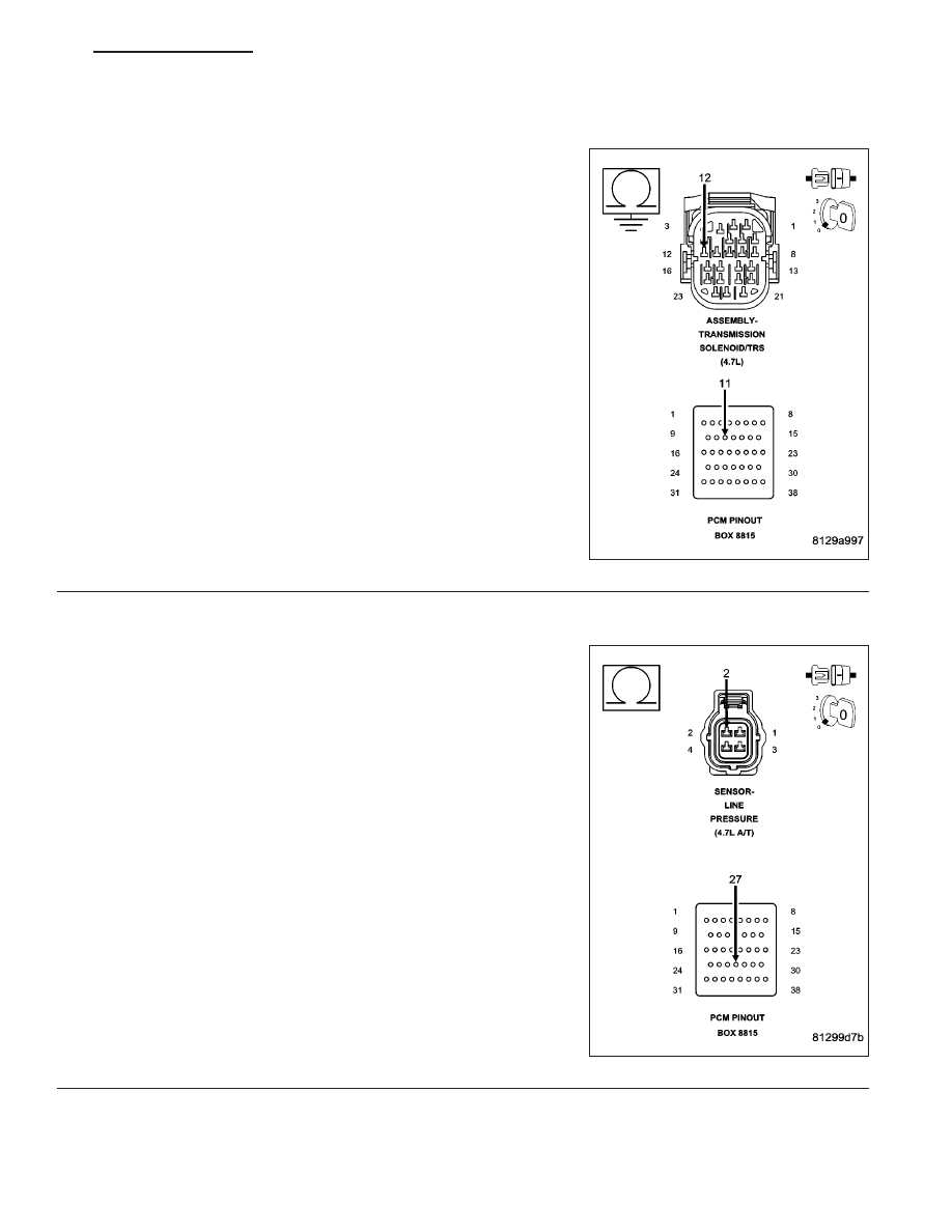
P0869-LINE PRESSURE HIGH (CONTINUED)
7.
(T140) PRESSURE CONTROL SOLENOID CONTROL CIRCUIT SHORT TO GROUND
Measure the resistance between ground and the (T140) Pressure
Control Solenoid Control circuit.
Is the resistance below 5.0 ohms?
Yes
>> Repair the (T140) Pressure Control Solenoid Control cir-
cuit for a short to ground.
Perform 45RFE/545RFE TRANSMISSION VERIFICATION
TEST - VER 1.
No
>> Go To 8
8.
(F856) 5-VOLT SUPPLY CIRCUIT OPEN
Measure the resistance of the (F856) 5-volt Supply circuit between the
Line Pressure Sensor harness connector to the appropriate terminal of
Miller tool #8815.
Is the resistance above 5.0 ohms?
Yes
>> Repair the (F856) 5-volt Supply circuit for an open.
Perform 45RFE/545RFE TRANSMISSION VERIFICATION
TEST - VER 1.
No
>> Go To 9
HB
AUTOMATIC TRANSMISSION 545RFE - ELECTRICAL DIAGNOSTICS
21 - 481