Dodge Durango (HB). Manual - part 1161


  Index      Dodge     Dodge Durango (HB) - service repair manual 2005 year


Search            


Content   ..  1159  1160  1161  1162   ..


Dodge Durango (HB). Manual - part 1161


P0715-INPUT SPEED SENSOR 1 CIRCUIT (CONTINUED)

5.

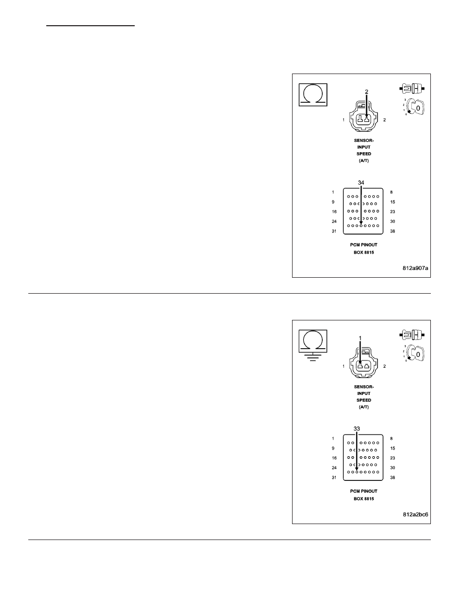
(T13) SPEED SENSOR GROUND CIRCUIT OPEN

Measure the resistance of the (T13) Speed Sensor Ground circuit from
the from the appropriate terminal of special tool #8815 to the Input
Speed Sensor harness connector.

Is the resistance above 5.0 ohms?

Yes

>> Repair the (T13) Speed Sensor Ground circuit for an

open.

Perform 42RLE TRANSMISSION VERIFICATION TEST -
VER 1.

No

>> Go To 6

6.

(T52) INPUT SPEED SENSOR SIGNAL CIRCUIT SHORT TO GROUND

Measure the resistance between ground and the (T52) Input Speed
Sensor Signal circuit.

Is the resistance Below 5.0 ohms?

Yes

>> Repair the (T52) Input Speed Sensor Signal circuit for a

short to ground.

Perform 42RLE TRANSMISSION VERIFICATION TEST -
VER 1.

No

>> Go To 7

HB

AUTOMATIC TRANSMISSION 42RLE - ELECTRICAL DIAGNOSTICS

21 - 49

P0715-INPUT SPEED SENSOR 1 CIRCUIT (CONTINUED)

7.

(T52) INPUT SPEED SENSOR SIGNAL CIRCUIT SHORT TO VOLTAGE

Disconnect the Output Speed Sensor harness connector.

Remove the Transmission Control Relay.

NOTE: Check connectors - Clean/repair as necessary.
Connect a jumper wire between the (A104) Fused B+ circuit and (T16)
Transmission Control Relay Output circuit in the Transmission Control
Relay connector.

Ignition on, engine not running.

Measure the voltage of the (T52) Input Speed Sensor Signal circuit.

Is the voltage above 0.5 volt?

Yes

>> Repair the (T52) Input Speed Sensor Signal circuit for a

short to voltage.

Perform 42RLE TRANSMISSION VERIFICATION TEST -
VER 1.

No

>> Go To 8

8.

(T13) SPEED SENSOR GROUND CIRCUIT SHORT TO VOLTAGE

NOTE: The jumper wire must still be connected.
Measure the voltage of the (T13) Speed Sensor Ground circuit.

Is the voltage above 0.5 volts?

Yes

>> Repair the (T13) Speed Sensor Ground circuit for a short

to voltage.

Perform 42RLE TRANSMISSION VERIFICATION TEST -
VER 1.

No

>> Go To 9

21 - 50

AUTOMATIC TRANSMISSION 42RLE - ELECTRICAL DIAGNOSTICS

HB

P0715-INPUT SPEED SENSOR 1 CIRCUIT (CONTINUED)

9.

POWERTRAIN CONTROL MODULE

Using the schematics as a guide, inspect the wiring and connectors. Repair as necessary. Pay particular attention
to all power and ground circuits.

If there are no possible causes remaining, view repair.

Repair

Replace the Powertrain Control Module per the Service Information. With the scan tool perform QUICK
LEARN.

Perform 42RLE TRANSMISSION VERIFICATION TEST - VER 1.

10.

INTERMITTENT WIRING AND CONNECTORS

The conditions necessary to set the DTC are not present at this time.

Using the schematics as a guide, inspect the wiring and connectors specific to this circuit.

Wiggle the wiring and connectors while checking for shorted and open circuits.

With the scan tool , check the EATX DTC EVENT DATA to help identify the conditions in which the DTC was set.

Were there any problems found?

Yes

>> Repair as necessary.

Perform 42RLE TRANSMISSION VERIFICATION TEST - VER 1.

No

>> Test Complete.

HB

AUTOMATIC TRANSMISSION 42RLE - ELECTRICAL DIAGNOSTICS

21 - 51

P0720-OUTPUT SPEED SENSOR CIRCUIT

42RLE MINI SPD SEN CKTS

21 - 52

AUTOMATIC TRANSMISSION 42RLE - ELECTRICAL DIAGNOSTICS

HB


Content   ..  1159  1160  1161  1162   ..