Dodge Durango (HB). Manual - part 1156


  Index      Dodge     Dodge Durango (HB) - service repair manual 2005 year


Search            


Content   ..  1154  1155  1156  1157   ..


Dodge Durango (HB). Manual - part 1156


P0706-TRANSMISSION RANGE SENSOR RATIONALITY (CONTINUED)

16.

TRS (T42) SENSE CIRCUIT SHORT TO VOLTAGE

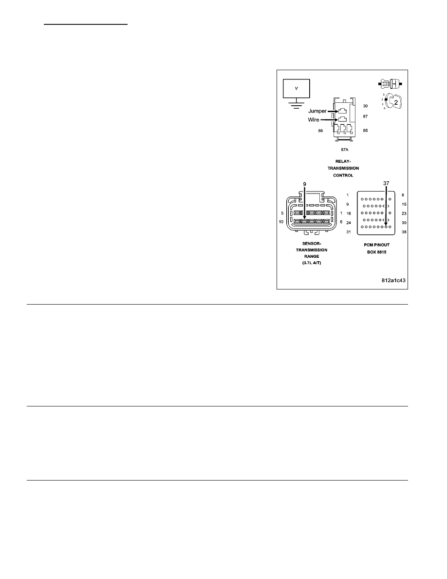
Remove the Transmission Control Relay.

NOTE: Check connectors - Clean/repair as necessary.
Connect a jumper wire between the (A104) Fused B+ circuit and the
(T16) Transmission Control Relay Output circuit in the Transmission
Control Relay connector.

Ignition on, engine not running.

Measure the voltage of the TRS (T42) Sense circuit.

Is the voltage above 0.5 volt?

Yes

>> Repair the TRS (T42) Sense circuit for a short to voltage.

Go To 19

No

>> Go To 17

17.

POWERTRAIN CONTROL MODULE

Using the schematics as a guide, inspect the wiring and connectors. Repair as necessary. Pay particular attention
to all power and ground circuits.

If there are no possible causes remaining, view repair.

Repair

Replace the Powertrain Control Module per the Service Information. With the scan tool perform QUICK
LEARN.

Go To 19

18.

CHECK AND ADJUST SHIFTER

If there are no possible causes remaining, view repair.

Repair

Adjust the Shift Linkage and/or cable per the Service Information.

Go To 19

HB

AUTOMATIC TRANSMISSION 42RLE - ELECTRICAL DIAGNOSTICS

21 - 29

P0706-TRANSMISSION RANGE SENSOR RATIONALITY (CONTINUED)

19.

PRNDL FAULT CLEARING PROCEDURE

With the scan tool, erase Transmission DTCs.

Cycle the ignition off, then start the vehicle.

Firmly apply the brakes and shift into Overdrive.

NOTE: NOTE: Vehicle must remain in Overdrive for at least 3.0 seconds.
With the brakes firmly applied, shift slowly through all gears (PRNDL) as least three times, pausing momentarily in
each gear.

NOTE: NOTE: If all the PRNDL lights box individually then the error was cleared.
Shift into park and turn the ignition off to the lock position.

Ignition on, engine not running.

With the DRBIII

T

, read Transmission DTCs.

Does the DTC P0706 reset, or do all the PRNDL indicators remain boxed in park or neutral?

Yes

>> Return to the symptom list and perform diagnostics for P0706 CHECK SHIFTER SIGNAL.

Go To 1

No

>> Test Complete.

Perform 42RLE TRANSMISSION VERIFICATION TEST - VER 1.

20.

INTERMITTENT WIRING AND CONNECTORS

The conditions necessary to set the DTC are not present at this time.

Using the schematics as a guide, inspect the wiring and connectors specific to this circuit.

Wiggle the wiring and connectors while checking for shorted and open circuits.

Check the Shift Linkage and cable for proper operation per the Service Information.

With the scan tool, check the EATX DTC EVENT DATA to help identify the conditions in which the DTC was set.

Were there any problems found?

Yes

>> Repair as necessary.

Go To 19

No

>> Test Complete.

21 - 30

AUTOMATIC TRANSMISSION 42RLE - ELECTRICAL DIAGNOSTICS

HB

P0711-TRANSMISSION TEMPERATURE SENSOR PERFORMANCE

42RLE MINI TRS CKTS

HB

AUTOMATIC TRANSMISSION 42RLE - ELECTRICAL DIAGNOSTICS

21 - 31

P0711-TRANSMISSION TEMPERATURE SENSOR PERFORMANCE (CONTINUED)

For the Transmission circuit diagram (Refer to 21 - TRANSMISSION/TRANSAXLE/AUTOMATIC - 42RLE - SCHE-
MATICS AND DIAGRAMS)

For a complete wiring diagram Refer to Section 8W.

When Monitored:
Continuously with the ignition on and engine running.

Set Condition:
DTC will set when the transmission temperature does not reach a normal operating temperature within a given
time frame. Time is variable due to ambient temperature. Approximate DTC set time is 10 to 35 minutes. The
following are starting temperature to warm up times to set this DTC: starting temp -40° C (-40° F) warm up
time 35 minutes, starting temp -28° C ( -20° F) 25 min, starting temp -6.6° C (20° F) 20 minutes, starting temp
15.5 ° C (60° F) 10 minutes. When the fault is set, calculated temperature is substituted for measured tem-
perature, however the fault code is stored only after three consecutive occurrences of the fault.

Possible Causes

RELATED TRANSMISSION TEMPERATURE DTC’S PRESENT

TRANSMISSION TEMPERATURE SENSOR

POWERTRAIN CONTROL MODULE

Always perform the Pre-Diagnostic Troubleshooting procedure before proceeding. (Refer to 21 - TRANSMIS-
SION/TRANSAXLE/AUTOMATIC - 42RLE - DIAGNOSIS AND TESTING).

Theory of Operation

The temperature sensor is used to sense the temperature of the transmission fluid. Transmission fluid temperature
can affect shift quality, torque converter operation and when or if some diagnostics are run. A failed temperature
sensor could affect the OBD diagnostics. If a problem occurs in the transmission temperature sensor circuit, trans-
mission temperature will be based on a calculated value.

Diagnostic Test

1.

DETERMINE IF RELATED TRANSMISSION TEMPERATURE DTCS ARE PRESENT

With the scan tool, check Transmission DTCs.

Are there any other Transmission Temperature Sensor related DTCs present?

Yes

>> Refer to the Transmission category and perform the appropriate diagnostic procedure.

Perform 42RLE TRANSMISSION VERIFICATION TEST - VER 1.

No

>> Go To 2

2.

CHECK TO SEE IF DTC IS ACTIVE

With the scan tool, view DTCs.

Is the status Active for this DTC or is the STARTS SINCE SET counter 2 or less?

Yes

>> Go To 3

No

>> Go To 6

21 - 32

AUTOMATIC TRANSMISSION 42RLE - ELECTRICAL DIAGNOSTICS

HB


Content   ..  1154  1155  1156  1157   ..