Dodge Durango (HB). Manual - part 1139


  Index      Dodge     Dodge Durango (HB) - service repair manual 2005 year


Search            


Content   ..  1137  1138  1139  1140   ..


Dodge Durango (HB). Manual - part 1139


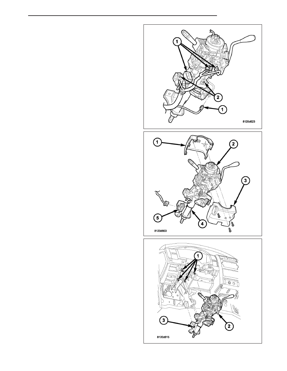
10. Disconnect the wiring harness connectors (1) to

the column.

11. Remove the shift cable from the column shift lever

actuator (Refer to 21 - TRANSMISSION/TRANS-
AXLE/AUTOMATIC - 32RH/GEAR SHIFT CABLE
- REMOVAL).

12. Release the shift cable from the column bracket

and remove it from the bracket.

13. Remove the SKIM module in order to disconnect

the electrical connector.

14. Remove the upper steering shaft coupler bolt and

slide the shaft down.

15. Remove the brake light switch (5) and discard

(Refer to 8 - ELECTRICAL/LAMPS/LIGHTING -
EXTERIOR/BRAKE LAMP SWITCH - REMOVAL).

16. Remove the four steering column mounting nuts

(3).

17. Lower the column from the mounting studs (1).

18. Remove the steering column assembly (2) from

the vehicle.

HB

COLUMN

19 - 9

INSTALLATION

WARNING: BEFORE SERVICING THE STEERING
COLUMN THE AIRBAG SYSTEM MUST BE DIS-
ARMED.

REFER

TO

ELECTRICAL

RESTRAINT

SYSTEM FOR SERVICE PROCEDURES. FAILURE
TO DO SO MAY RESULT IN ACCIDENTAL DEPLOY-
MENT OF THE AIRBAG AND POSSIBLE PER-
SONAL INJURY.

CAUTION: All fasteners must be torqued to speci-
fication to ensure proper operation of the steering
column.

1. Position the steering column (2) on the dash panel

support (1) and loosely install the mounting nuts
(3).

2. Firmly slide the steering column (2) upward against

the studs (1) in dash panel and hand tighten the
nuts (3).

3. Install the steering shaft coupler on the steering shaft and loosely install a new bolt.

4. Center steering column (2) in dash opening and tighten mounting nuts (3) to 28 N·m (250 in. lbs.).

NOTE: Torque the upper left nut first then the lower right nut. Then torque the lower left nut then the upper
right nut.

NOTE: A new bolt must be used for reinstallation.

5. Tighten the coupler bolt to 38 N·m (28 ft. lbs.).

6. Install a new brake light switch (5) (Refer to 8 -

ELECTRICAL/LAMPS/LIGHTING

-

EXTERIOR/

BRAKE LAMP SWITCH - REMOVAL).

7. Install the shifter cable. (Refer to 21 - TRANSMIS-

SION/TRANSAXLE/AUTOMATIC

-

32RH/GEAR

SHIFT CABLE - INSTALLATION)

19 - 10

COLUMN

HB

8. Connect the wiring harness (1) to the column (2).

9. Install the SKIM module.

10. Install the clockspring (Refer to 8 - ELECTRICAL/

RESTRAINTS/CLOCKSPRING - REMOVAL).

11. Install the shrouds (1&3).

12. Install the steering column opening reinforcement

(1).

HB

COLUMN

19 - 11

13. Install the steering column opening cover (2)

(Refer to 23 - BODY/INSTRUMENT PANEL/
STEERING

COLUMN

OPENING

COVER

-

INSTALLATION).

14. Align the spline on the steering wheel hub to shaft

(4).

15. Then install the steering wheel (1) and install a

new bolt (2). Tighten the bolt to 61 N·m (45 ft.
lbs.).

16. Install the airbag (Refer to 8 - ELECTRICAL/RE-

STRAINTS/DRIVER AIRBAG - INSTALLATION).

17. Install the tilt lever handle.

18. Install the negative battery terminal.

19. Test the operation of the horn, Electronic PRNDL

Indicator, lights and any other functions that are
steering column operated.

SPECIFICATIONS

TORQUE CHART

TORQUE SPECIFICATIONS

DESCRIPTION

N·m

Ft. Lbs.

In. Lbs.

Tilt Lever Release Knob

Bracket

Mounting Screws

4.5

40

Gear Shift Lever Assembly

Mounting Screws

12

105

Steering Column

Mounting Nuts

28

250

Steering Wheel

Bolt

61

45

Steering Coupler Shaft

Upper Pinch Bolt

38

28

Steering Coupler Shaft

Lower Pinch Bolt

38

28

Toe Plate

Nuts

12

105

19 - 12

COLUMN

HB


Content   ..  1137  1138  1139  1140   ..