Content .. 1077 1078 1079 1080 ..
Dodge Durango (HB). Manual - part 1079
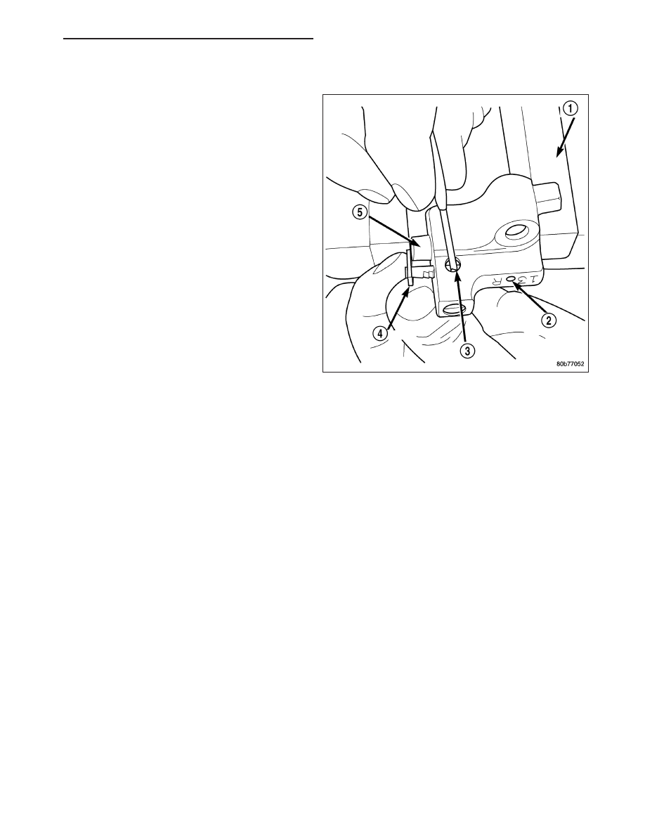
INSTALLATION
1. Using a vise, lightly compress the secondary chain
tensioner piston until the piston step is flush with
the tensioner body. Using a pin or suitable tool,
release ratchet pawl by pulling pawl back against
spring force through access hole on side of ten-
sioner. While continuing to hold pawl back, Push
ratchet device to approximately 2 mm from the ten-
sioner body. Install Special Tool 8514 lock pin (3)
into hole on front of tensioner (2). Slowly open vise
to transfer piston spring force to lock pin.
2. Position primary chain tensioner over oil pump and insert bolts into lower two holes on tensioner bracket. Tighten
bolts to 28 N·m (250 in. lbs.).
CAUTION: Overtightening the tensioner arm torx
T
bolt can cause severe damage to the cylinder head.
Tighten torx
T
bolt to specified torque only.
3. Install right side chain tensioner arm. Apply Mopar
T
Lock N, Seal to torx
T
bolt, tighten bolt to 17 N·m (150 in.
lbs.).
NOTE: The silver bolts retain the guides to the cylinder heads and the black bolts retain the guides to the
engine block.
4. Install the left side chain guide. Tighten the bolts to 28 N·m (250 in. lbs.).
CAUTION: Overtightening the tensioner arm torx
T
bolt can cause severe damage to the cylinder head.
Tighten torx
T
bolt to specified torque only.
5. Install left side chain tensioner arm. Apply Mopar
T
Lock N, Seal to torx
T
bolt, tighten bolt to 17 N·m (150 in. lbs.).
6. Install the right side chain guide. Tighten the bolts to 28 N·m (250 in. lbs.).
HB
ENGINE - 4.7L SERVICE INFORMATION
9 - 1315