Content .. 1045 1046 1047 1048 ..
Dodge Durango (HB). Manual - part 1047
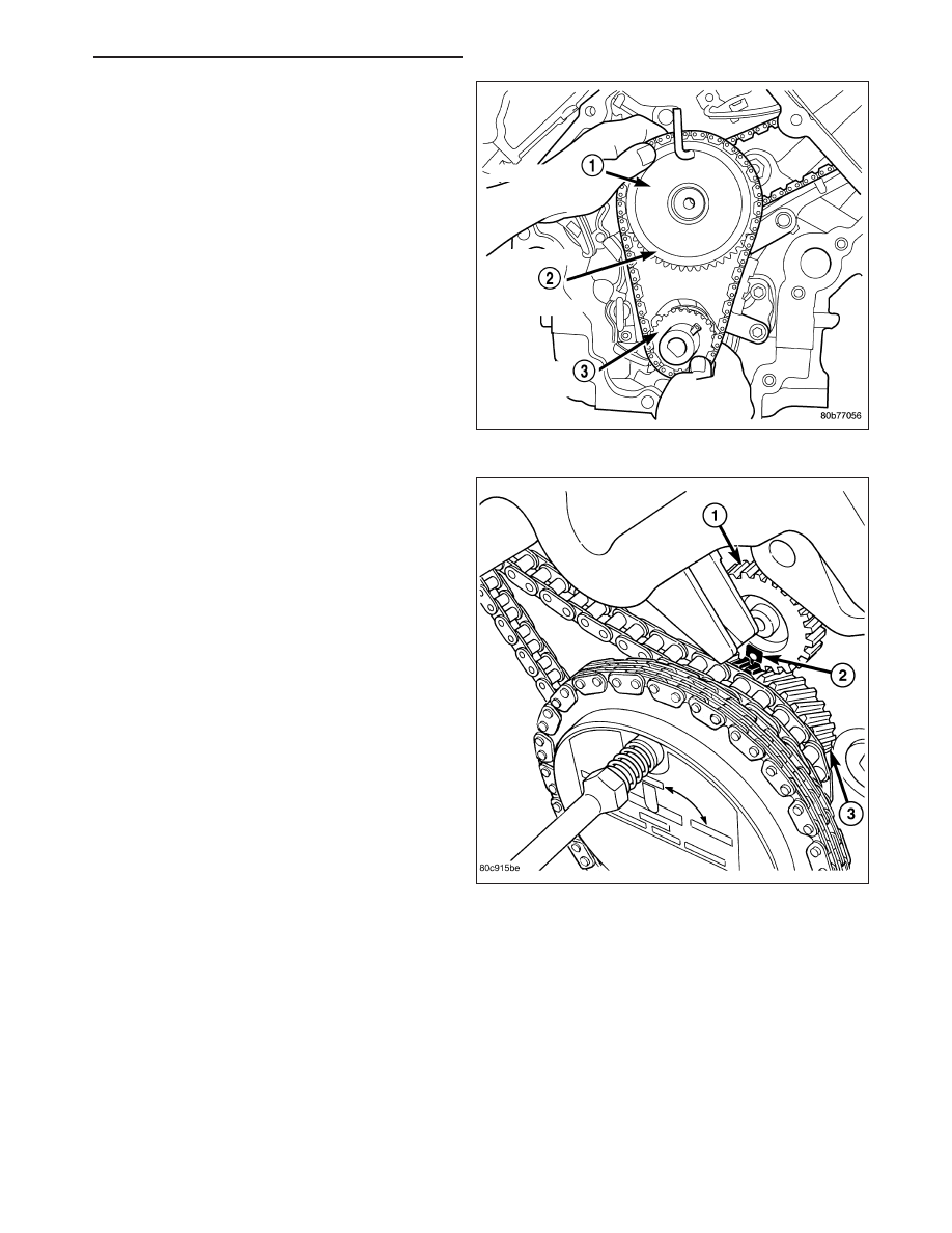
7. Install
both
secondary
chains
onto
the
idler
sprocket (2). Align two plated links on the second-
ary chains to be visible through the two lower
openings on the idler sprocket (4 o’clock and 8
o’clock). Once the secondary timing chains are
installed, position special tool 8429 ( 1) to hold
chains in place for installation.
8. Align primary chain double plated links with the tim-
ing mark at 12 o’clock on the idler sprocket. Align
the primary chain single plated link with the timing
mark at 6 o’clock on the crankshaft sprocket.
9. Lubricate idler shaft and bushings with clean
engine oil.
NOTE: The idler sprocket must be timed to the
counterbalance shaft drive gear before the idler
sprocket is fully seated.
10. Install all chains, crankshaft sprocket, and idler
sprocket as an assembly. After guiding both sec-
ondary chains through the block and cylinder
head openings, affix chains with a elastic strap or
equivalent. This will maintain tension on chains to
aid in installation. Align the timing mark (2) on the
idler sprocket gear (3) to the timing mark on the
counterbalance shaft drive gear (1), then seat
idler sprocket fully. Before installing idler sprocket
bolt, lubricate washer with oil, and tighten idler
sprocket assembly retaining bolt to 34 N·m (25 ft.
lbs.).
NOTE: It will be necessary to slightly rotate cam-
shafts for sprocket installation.
11. Align left camshaft sprocket “L” dot to plated link
on chain.
12. Align right camshaft sprocket “R” dot to plated link
on chain.
CAUTION: Remove excess oil from the camshaft
sprocket bolt. Failure to do so can result in over-
torque of bolt resulting in bolt failure.
13. Remove Special Tool 8429, then attach both sprockets to camshafts. Remove excess oil from bolts, then Install
sprocket bolts, but do not tighten at this time.
14. Verify that all plated links are aligned with the marks on all sprockets and the “V6” marks on camshaft sprockets
are at the 12 o’clock position.
CAUTION: Ensure the plate between the left secondary chain tensioner and block is correctly installed.
15. Install both secondary chain tensioners. Tighten bolts to 28 N·m (250 in. lbs.).
NOTE: Left and right secondary chain tensioners are not common.
16. Remove all locking pins (3) from tensioners.
HB
ENGINE - 3.7L SERVICE INFORMATION
9 - 1187