Dodge Durango (HB). Manual - part 1038


  Index      Dodge     Dodge Durango (HB) - service repair manual 2005 year


Search            


Content   ..  1036  1037  1038  1039   ..


Dodge Durango (HB). Manual - part 1038


4WD

1. Disconnect the negative cable from the battery.

CAUTION: Remove the viscous fan before raising engine. Failure to do so may cause damage to the fan
blade, fan clutch and fan shroud.

2. Remove the viscous fan (Refer to 7 - COOLING/ENGINE/FAN DRIVE VISCOUS CLUTCH - REMOVAL).

3. Raise the vehicle.

4. Remove the skid plate.

5. Remove the front crossmember.

6. Remove the engine oil filter.

7. Remove the oil drain trough.

8. Support the engine with a suitable jack and a block of wood across the full width of the engine oil pan.

9. Support the front axle with a suitable jack.

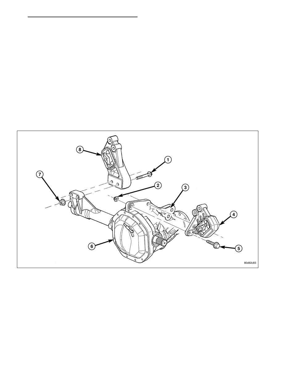
10. Remove the (4) bolts that attach the engine mounts to the front axle.

11. Remove the (3) bolts that attach the front axle to the left engine bracket.

12. Lower the front axle.

13. Remove the (6) through bolts

14. Raise the engine far enough to be able to remove the left and right engine mounts.

HB

ENGINE - 3.7L SERVICE INFORMATION

9 - 1151

15. Remove the engine mounts.

INSTALLATION

2WD

NOTE: For mount to engine block and left engine
bracket to front axle bolts, apply Mopar

T

Lock and

Seal Adhesive, Medium Strength Threadlocker.

1. Install the right and left side engine mounts to the

engine block with (8) bolts. Torque bolts to 54 N·m
(40 ft. lbs.).

2. Insert the (2) through bolts into the right and left

side engine mounts and loose assemble the two
nuts onto the through bolts.

3. Lower the engine until the through bolts rest onto

the slots in the frame brackets.

4. Tighten the through bolt nuts to 94 N·m (70 ft. lbs.).

5. Install the oil drain trough.

6. Install the engine oil filter.

7. Lower the vehicle.

8. Install the viscous fan (Refer to 7 - COOLING/ENGINE/FAN DRIVE VISCOUS CLUTCH - REMOVAL).

9. Reconnect the negative battery cable.

9 - 1152

ENGINE - 3.7L SERVICE INFORMATION

HB

4WD

NOTE: For mount to engine block and left engine bracket to front axle bolts, apply Mopar

T

Lock and Seal

Adhesive, Medium Strength Threadlocker.

1. Install the right and left side engine mounts to the front axle. Torque nuts to 94 N·m (70 ft. lbs.).

2. Raise the front axle into the frame and install the left and right side through bolts. Torque nuts to 94 N·m (70 ft.

lbs.).

3. Insert the two upper through bolts into the right and left side engine mounts and loose assemble the two nuts

onto the through bolts.

4. Lower the engine until the left and right side engine brackets rest on the through bolts, and the lower engine

bracket through holes align with the engine mounts, and the left engine bracket holes align with the front axle
slots.

5. Loose assemble the (3) bolts that attach the front axle to the left engine bracket.

6. Loose assemble the lower through bolts.

7. Torque the nuts for the (4) through bolts to 101 N·m (75 ft. lbs.).

8. Torque the (3) bolts that attach the front axle to the left engine bracket to 101 N·m (75 ft. lbs.).

9. Install the oil drain trough.

10. Install the engine oil filter.

11. Install the front crossmember.

12. Install the skid plate.

13. Lower the vehicle.

14. Install the viscous fan (Refer to 7 - COOLING/ENGINE/FAN DRIVE VISCOUS CLUTCH - REMOVAL).

15. Reconnect the negative battery cable.

HB

ENGINE - 3.7L SERVICE INFORMATION

9 - 1153

MOUNT-ENGINE REAR

REMOVAL

1. Raise the vehicle on a hoist.

2. Using a suitable jack, support transmission.

3. Remove the nuts from the transmission mount.

4. Remove the two bolts that attach the transmission

mount to the engine bracket.

5. Raise the transmission enough to remove the

mount from the crossmember.

6. Remove the mount.

INSTALLATION

NOTE: Threadlocking compound must be applied to the bolts before installation.

1. Install the two bolts that attach the transmission mount to the transmission bracket.

2. Torque the bolts to 61N·m (45 ft.lbs.) torque.

3. Lower the transmission so the transmission mount rests on the crossmember, and the studs of the transmission

mount are aligned in the slots in the crossmember.

4. Install the nuts onto the transmission mount studs through the crossmember access slot.

5. Torque the nuts to 54N·m (40 ft. lbs.).

LUBRICATION

DESCRIPTION

The lubrication system is a full flow filtration pressure feed type.

9 - 1154

ENGINE - 3.7L SERVICE INFORMATION

HB


Content   ..  1036  1037  1038  1039   ..