Index Dodge Dodge Durango (HB) - service repair manual 2005 year
Search
Content .. 93 94 95 96 ..
Dodge Durango (HB). Manual - part 95
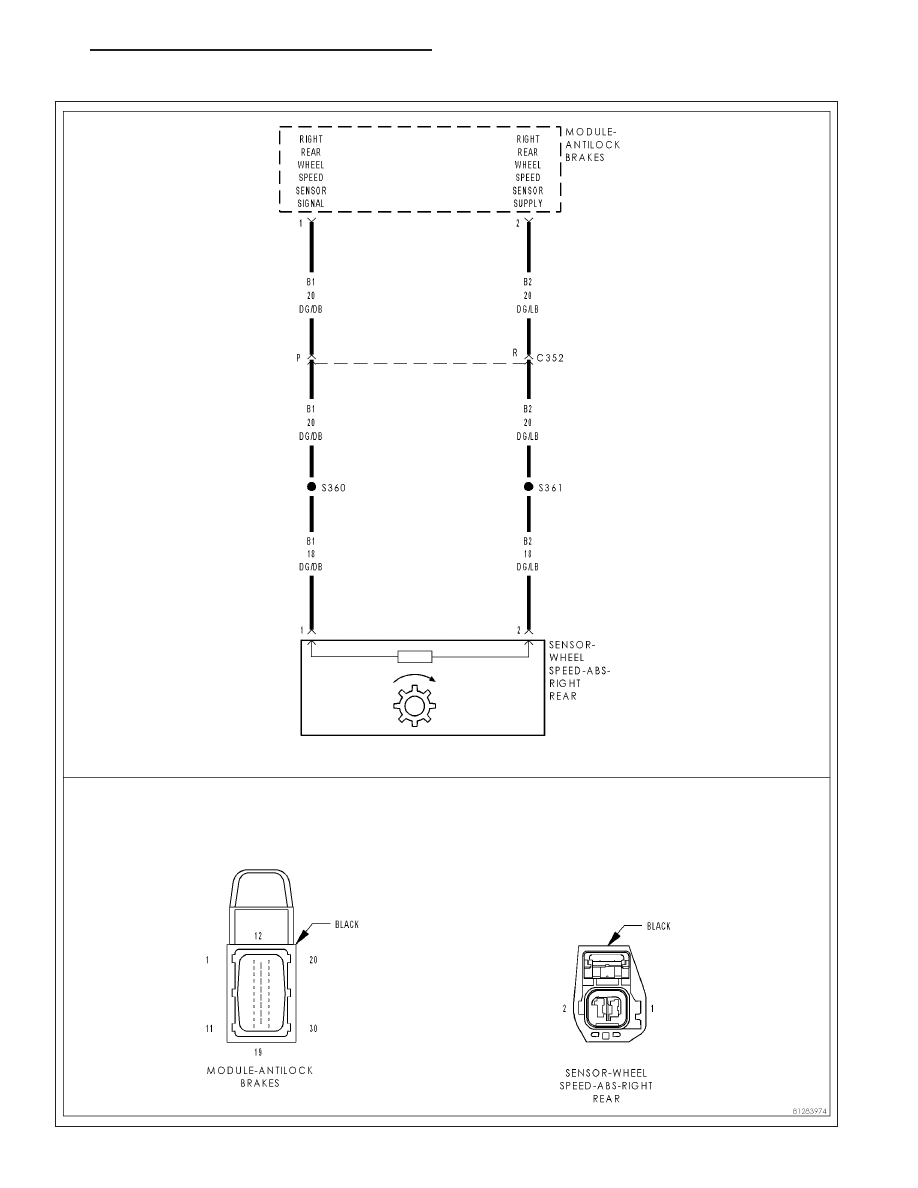
C102B–RIGHT REAR WHEEL SPEED SENSOR CIRCUIT
HB
BRAKES - ABS ELECTRICAL DIAGNOSTICS
5 - 159