Dodge Dakota (R1). Manual - part 874
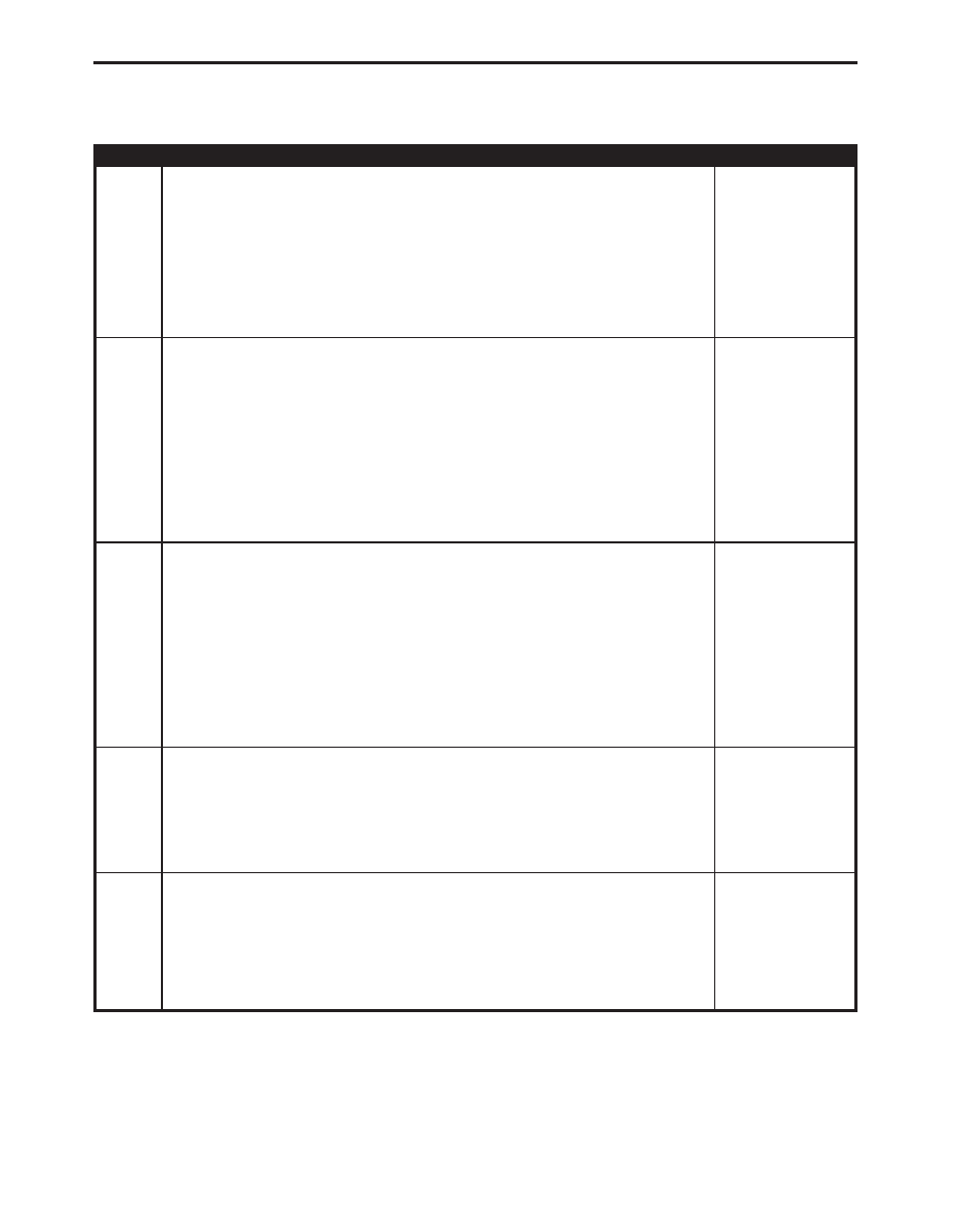
TEST
ACTION
APPLICABILITY
4
Turn the ignition off.
Disconnect the clockspring 6-way harness connector (instrument panel wiring side).
Turn the ignition on.
With the DRBIII
t in Sensors, read the S/C Switch volts.
Did the S/C Switch volts change to 5.0 volts?
All
Yes
→
Replace the Clockspring.
Perform POWERTRAIN VERIFICATION TEST VER - 4.
No
→
5
Turn the ignition off.
Disconnect the S/C ON/OFF Switch harness connector.
Disconnect the PCM harness connectors.
Note: Check connectors - Clean/repair as necessary.
Measure the resistance between the S/C Signal Circuit and the Sensor Ground
Circuit at the ON/OFF switch harness connector.
Is the resistance below 5.0 ohms?
All
Yes
→
Repair S/C Signal Circuit shorted to Sensor Ground.
Perform POWERTRAIN VERIFICATION TEST VER - 4.
No
→
6
Turn the ignition off.
Disconnect the S/C ON/OFF Switch harness connector.
Disconnect the PCM harness connectors.
Note: Check connectors - Clean/repair as necessary.
Measure the resistance between the S/C Switch Signal circuit and ground (B-) at S/C
ON/OFF Switch harness connector.
Is the resistance below 5.0 ohms?
All
Yes
→
Repair S/C Switch Signal Circuit for a short to ground.
Perform POWERTRAIN VERIFICATION TEST VER - 4.
No
→
7
If there are no possible causes remaining, replace the Powertrain Control Module.
View repair options.
All
Repair
Replace and program the Powertrain Control Module in accor-
dance with the Service Information.
Perform POWERTRAIN VERIFICATION TEST VER - 4.
8
Turn the ignition off.
Using the Schematics as a guide, inspect the Wiring and Connectors.
Were any problems found?
All
Yes
→
Repair as necessary.
Perform POWERTRAIN VERIFICATION TEST VER - 4.
No
→
Test Complete.
228
SPEED CONTROL
P1597-SPEED CONTROL SWITCH ALWAYS LOW —
Continued