Dodge Dakota (R1). Manual - part 811


  Index      Dodge     Dodge Dakota (R1) - service repair manual 2000 year


Search            


Content   ..  809  810  811  812   ..


Dodge Dakota (R1). Manual - part 811


purge solenoid for damage or leaks. If a leak is
present, a Diagnostic Trouble Code (DTC) may
be set.

(3) Connect electrical connector to LDP.
(4) Install battery tray. Refer to 8, Battery for pro-

cedures.

(5) Install PDC to fender and battery tray (snaps

on to battery tray).

(6) Install LDP filter to battery tray (one clip).
(7) Install connecting hose to bottom of LDP filter.
(8) Connect battery temperature sensor pigtail

wiring harness.

(9) Install battery. Refer to 8, Battery for proce-

dures.

(10) Connect negative battery cable to battery.

PCV VALVE

DESCRIPTION - 3.9L/5.2L/5.9L

All 3.9L V-6 and 5.2/5.9L V-8 are equipped with a

closed crankcase ventilation system and a positive
crankcase ventilation (PCV) valve. The 2.5L 4–cylin-
der engine is not equipped with a PCV valve. Refer
to Crankcase Ventilation System—2.5L Engine for
information.

This system consists of a PCV valve mounted on

the cylinder head (valve) cover with a hose extending
from the valve to the intake manifold (Fig. 8).
Another hose connects the opposite cylinder head
(valve) cover to the air cleaner housing to provide a
source of clean air for the system. A separate crank-
case breather/filter is not used.

DESCRIPTION - 4.7L

The 4.7L V-8 engine is equipped with a closed

crankcase ventilation system and a Positive Crank-
case Ventilation (PCV) valve.

This system consists of:
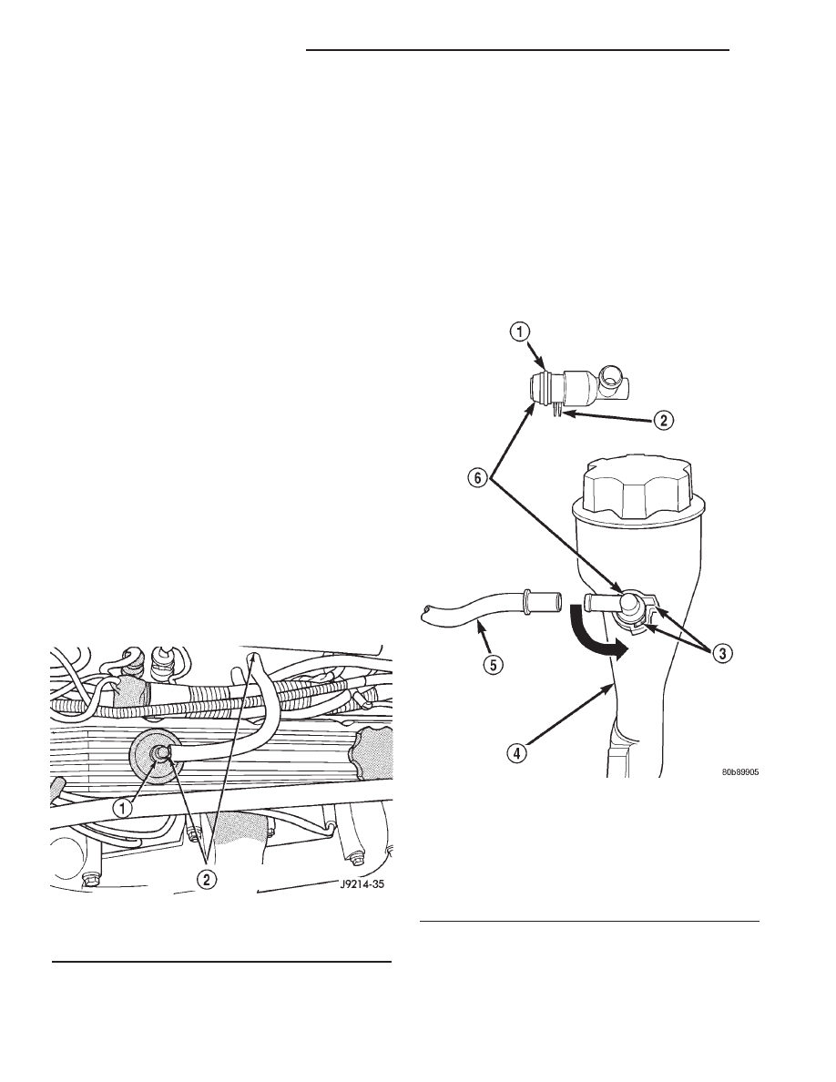
• a PCV valve mounted to the oil filler housing

(Fig. 9). The PCV valve is sealed to the oil filler
housing with an o-ring.

• the air cleaner housing

• two interconnected breathers threaded into the

rear of each cylinder head (Fig. 10).

• tubes and hose to connect the system compo-

nents.

Fig. 8 PCV Valve/Hose—Typical

1 - PCV VALVE
2 - PCV VALVE HOSE CONNECTIONS

Fig. 9 PCV Valve/Oil Filler Tube (Housing)—4.7L

Engine

1 - O-RING
2 - LOCATING TABS
3 - CAM LOCK
4 - OIL FILLER TUBE
5 - PCV LINE/HOSE
6 - PCV VALVE

25 - 28

EVAPORATIVE EMISSIONS

AN

LEAK DETECTION PUMP (Continued)

OPERATION - 3.9L/5.2L/5.9L

The PCV system operates by engine intake mani-

fold vacuum (Fig. 11). Filtered air is routed into the
crankcase through the air cleaner hose. The metered
air, along with crankcase vapors, are drawn through
the PCV valve and into a passage in the intake man-
ifold. The PCV system manages crankcase pressure
and meters blow by gases to the intake system,
reducing engine sludge formation.

The PCV valve contains a spring loaded plunger.

This plunger meters the amount of crankcase vapors
routed into the combustion chamber based on intake
manifold vacuum.

When the engine is not operating or during an

engine pop-back, the spring forces the plunger back
against the seat (Fig. 12). This will prevent vapors
from flowing through the valve.

During periods of high manifold vacuum, such as

idle or cruising speeds, vacuum is sufficient to com-
pletely compress spring. It will then pull the plunger
to the top of the valve (Fig. 13). In this position there
is minimal vapor flow through the valve.

Fig. 10 PCV System Hoses/Tubes—4.7L Engine

1 - FRESH AIR FITTING
2 - CONNECTING TUBES/HOSES
3 - CRANKCASE BREATHERS (2)
4 - RUBBER HOSE
5 - AIR CLEANER RESONATOR

Fig. 11 Typical Closed Crankcase Ventilation

System

1 - THROTTLE BODY
2 - AIR CLEANER
3 - AIR INTAKE
4 - PCV VALVE
5 - COMBUSTION CHAMBER
6 - BLOW-BY GASES
7 - CRANKCASE BREATHER/FILTER

Fig. 12 Engine Off/Engine Pop Back—No Vapor

Flow

Fig. 13 High Intake Manifold Vacuum—Minimal

Vapor Flow

AN

EVAPORATIVE EMISSIONS

25 - 29

PCV VALVE (Continued)

During periods of moderate manifold vacuum, the

plunger is only pulled part way back from inlet. This
results in maximum vapor flow through the valve
(Fig. 14).

OPERATION - 4.7L

The PCV system operates by engine intake mani-

fold vacuum. Filtered air is routed into the crankcase
through the air cleaner hose and crankcase breath-
ers. The metered air, along with crankcase vapors,
are drawn through the PCV valve and into a passage
in the intake manifold. The PCV system manages
crankcase pressure and meters blow-by gases to the
intake system, reducing engine sludge formation.

The PCV valve contains a spring loaded plunger.

This plunger meters the amount of crankcase vapors
routed into the combustion chamber based on intake
manifold vacuum.

TYPICAL PCV valves are shown in (Fig. 15), (Fig.

16) and (Fig. 17).

When the engine is not operating, or during an

engine pop-back, the spring forces the plunger back
against the seat (Fig. 15). This will prevent vapors
from flowing through the valve.

During periods of high manifold vacuum, such as

idle or cruising speeds, vacuum is sufficient to com-
pletely compress spring. It will then pull the plunger
to the top of the valve (Fig. 16). In this position there
is minimal vapor flow through the valve.

During periods of moderate manifold vacuum, the

plunger is only pulled part way back from inlet. This
results in maximum vapor flow through the valve
(Fig. 17).

DIAGNOSIS AND TESTING - PCV VALVE
TEST—3.9/5.2/5.9L ENGINE

(1) With engine idling, remove the PCV valve from

cylinder head (valve) cover. If the valve is not
plugged, a hissing noise will be heard as air passes
through the valve. Also, a strong vacuum should be
felt at the valve inlet (Fig. 18).

Fig. 14 Moderate Intake Manifold Vacuum—

Maximum Vapor Flow

Fig. 15 Engine Off or Engine Pop-Back—No Vapor

Flow

Fig. 16 High Intake Manifold Vacuum—Minimal

Vapor Flow

Fig. 17 Moderate Intake Manifold Vacuum—

Maximum Vapor Flow

Fig. 18 Vacuum Check at PCV

1 - PCV VALVE GROMMET
2 - PCV HOSE
3 - PCV VALVE
4 - VACUUM MUST BE FELT AGAINST FINGER
5 - ENGINE VALVE COVER

25 - 30

EVAPORATIVE EMISSIONS

AN

PCV VALVE (Continued)

(2) Return the PCV valve into the valve cover.

Remove the fitting and air hose at the opposite valve
cover. Loosely hold a piece of stiff paper, such as a
parts tag, over the opening (rubber grommet) at the
valve cover (Fig. 19).

(3) The paper should be drawn against the opening

in the valve cover with noticeable force. This will be
after allowing approximately one minute for crank-
case pressure to reduce.

(4) Turn engine off and remove PCV valve from

valve cover. The valve should rattle when shaken
(Fig. 20).

(5) Replace the PCV valve and retest the system if

it does not operate as described in the preceding
tests. Do not attempt to clean the old PCV valve.

(6) If the paper is not held against the opening in

valve cover after new valve is installed, the PCV
valve hose may be restricted and must be replaced.
The passage in the intake manifold must also be
checked and cleaned.

(7) To clean the intake manifold fitting, turn a 1/4

inch drill (by hand) through the fitting to dislodge
any solid particles. Blow out the fitting with shop air.
If necessary, use a smaller drill to avoid removing
any metal from the fitting.

DIAGNOSIS AND TESTING - PCV VALVE/PCV
SYSTEM TEST—4.7L V-8 ENGINE

(1) Disconnect PCV line/hose (Fig. 21) by discon-

necting rubber connecting hose at PCV valve fitting.

(2) Remove PCV valve at oil filler tube by rotating

PCV valve downward until locating tabs have been
freed at cam lock (Fig. 21). After tabs have cleared,
pull valve straight out from filler tube. To prevent
damage to PCV valve locating tabs, valve must
be pointed downward for removal. Do not force
valve from oil filler tube.

(3) After valve is removed, check condition of valve

o-ring (Fig. 21). Also, PCV valve should rattle when
shaken.

(4) Reconnect PCV valve to its connecting line/

hose.

(5) Start engine and bring to idle speed.
(6) If valve is not plugged, a hissing noise will be

heard as air passes through valve. Also, a strong vac-
uum should be felt with a finger placed at valve
inlet.

(7) If vacuum is not felt at valve inlet, check line/

hose for kinks or for obstruction. If necessary, clean
out intake manifold fitting at rear of manifold. Do
this by turning a 1/4 inch drill (by hand) through the
fitting to dislodge any solid particles. Blow out the
fitting with shop air. If necessary, use a smaller drill
to avoid removing any metal from the fitting.

(8) Do not attempt to clean the old PCV valve.
(9) Return PCV valve back to oil filler tube by

placing valve locating tabs (Fig. 21) into cam lock.
Press PCV valve in and rotate valve upward. A slight
click will be felt when tabs have engaged cam lock.
Valve should be pointed towards rear of vehicle.

(10) Connect PCV line/hose and connecting rubber

hose to PCV valve.

(11) Disconnect rubber hose from fresh air fitting

at left side of air cleaner resonator box (Fig. 22).
Start engine and bring to idle speed. Hold a piece of

Fig. 19 Vacuum Check at Valve Cover Opening

1 - STIFF PAPER PLACED OVER RUBBER GROMMET
2 - RUBBER GROMMET
3 - VALVE COVER
4 - FITTING REMOVED FROM VALVE COVER
5 - AIR TUBE

Fig. 20 Shake

1 - PCV VALVE GROMMET
2 - PCV VALVE
3 - PCV VALVE MUST RATTLE WHEN SHAKEN

AN

EVAPORATIVE EMISSIONS

25 - 31

PCV VALVE (Continued)


Content   ..  809  810  811  812   ..