Dodge Dakota (R1). Manual - part 807
(M)
Malfunction Indicator Lamp (MIL) illuminated during engine operation if this DTC was recorded
(depending if required by CARB and/or EPA). MIL is displayed as an engine icon on instrument panel.
(G)
Generator lamp illuminated
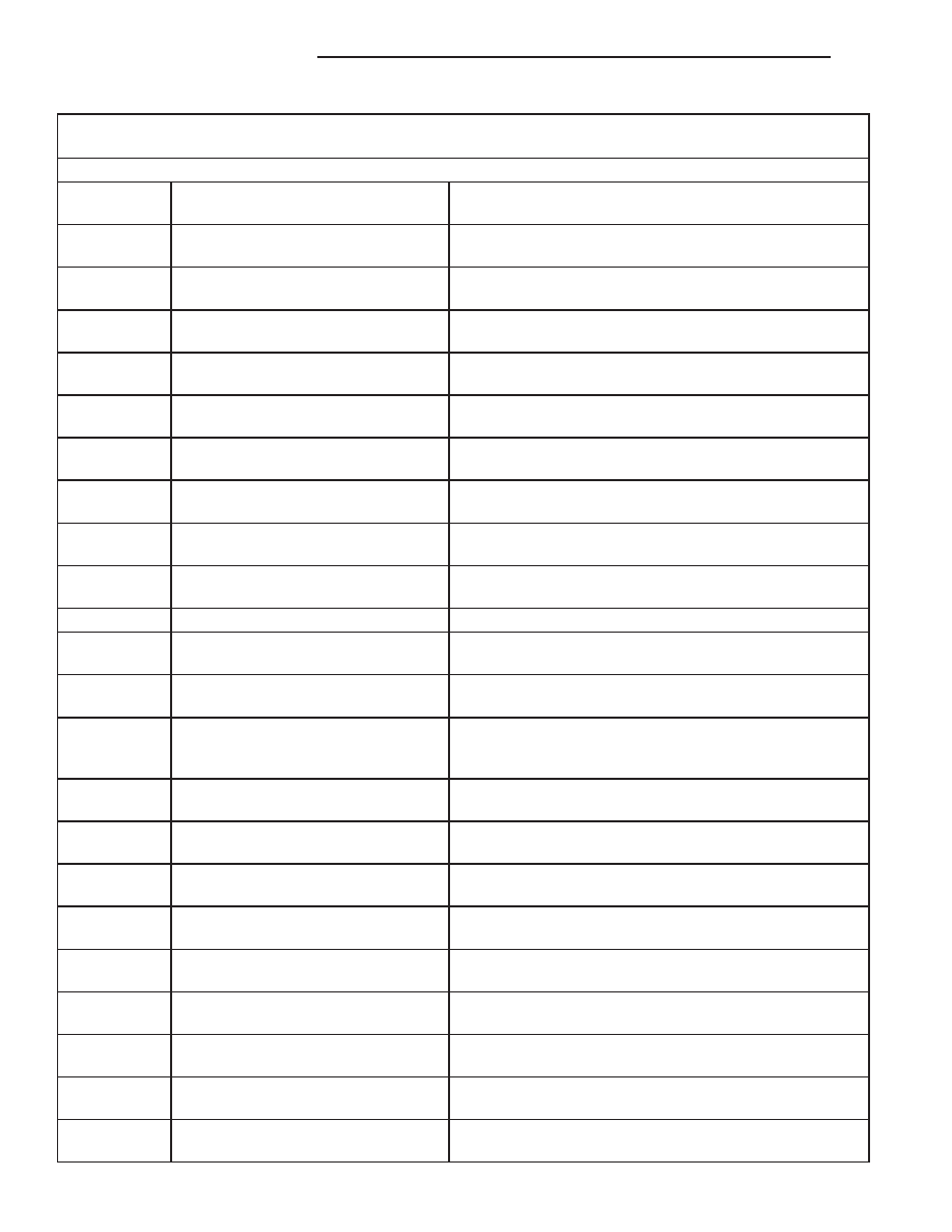
Generic Scan
Tool P-Code
DRB Scan Tool Display
Brief Description of DTC
P1480
PCV Solenoid Circuit
An open or shorted condition detected in the PCV
solenoid circuit.
P1481
EATX RPM Pulse Perf
EATX RPM pulse generator signal for misfire detection
does not correlate with expected value.
P1482
Catalyst Temperature Sensor Circuit
Shorted Low
Catalyst temperature sensor circuit shorted low.
P1483
Catalyst Temperature Sensor Circuit
Shorted High.
Catalyst temperature sensor circuit shorted high.
P1484
Catalytic Converter Overheat
Detected
A catalyst overheat condition has been detected by the
catalyst temperature sensor.
P1485
Air Injection Solenoid Circuit
An open or shorted condition detected in the air assist
solenoid circuit.
P1486
Evap Leak Monitor Pinched Hose
Found
LDP has detected a pinched hose in the evaporative hose
system.
P1487
Hi Speed Rad Fan CTRL Relay
Circuit
An open or shorted condition detected in the control
circuit of the #2 high speed radiator fan control relay.
P1488
Auxiliary 5 Volt Supply Output Too
Low
Auxiliary 5 volt sensor feed is sensed to be below an
acceptable limit.
P1488
5 Volt Supply Voltage Low
Sensor supply voltage for ECM sensors is too low.
P1489
High Speed Fan CTRL Relay Circuit
An open or shorted condition detected in the control
circuit of the high speed radiator fan control relay.
P1490
Low Speed Fan CTRL Relay Circuit
An open or shorted condition detected in control circuit of
the low speed radiator fan control relay.
P1491
Rad Fan Control Relay Circuit
An open or shorted condition detected in the radiator fan
control relay control circuit. This includes PWM solid state
relays.
P1492
Ambient/Batt Temp Sen Volts Too
High
External temperature sensor input above acceptable
voltage.
P1492 (M)
Ambient/Batt Temp Sensor Volts Too
High
Battery temperature sensor input voltage above an
acceptable range.
P1493 (M)
Ambient/Batt Temp Sen Volts Too
Low
External temperature sensor input below acceptable
voltage.
P1493 (M)
Ambient/Batt Temp Sen Volts Too
Low
Battery temperature sensor input voltage below an
acceptable range.
P1494 (M)
Leak Detection Pump Sw or
Mechanical Fault
Incorrect input state detected for the Leak Detection
Pump (LDP) pressure switch.
P1495
Leak Detection Pump Solenoid
Circuit
An open or shorted condition detected in the Leak
Detection Pump (LDP) solenoid circuit.
P1496
5 Volt Supply, Output Too Low
5 volt sensor feed is sensed to be below an acceptable
limit. ( less than 4v for 4 sec )
P1498
High Speed Rad Fan Ground CTRL
Rly Circuit
An open or shorted condition detected in the control
circuit of the #3 high speed radiator fan control relay.
P1499
Hydraulic cooling fan solenoid circuit
An open or shorted condition detected in the cooling fan
control solenoid circuit.
25 - 12
EMISSIONS CONTROL
AN
EMISSIONS CONTROL (Continued)