Dodge Dakota (R1). Manual - part 677


  Index      Dodge     Dodge Dakota (R1) - service repair manual 2000 year


Search            


Content   ..  675  676  677  678   ..


Dodge Dakota (R1). Manual - part 677


GEARTRAIN

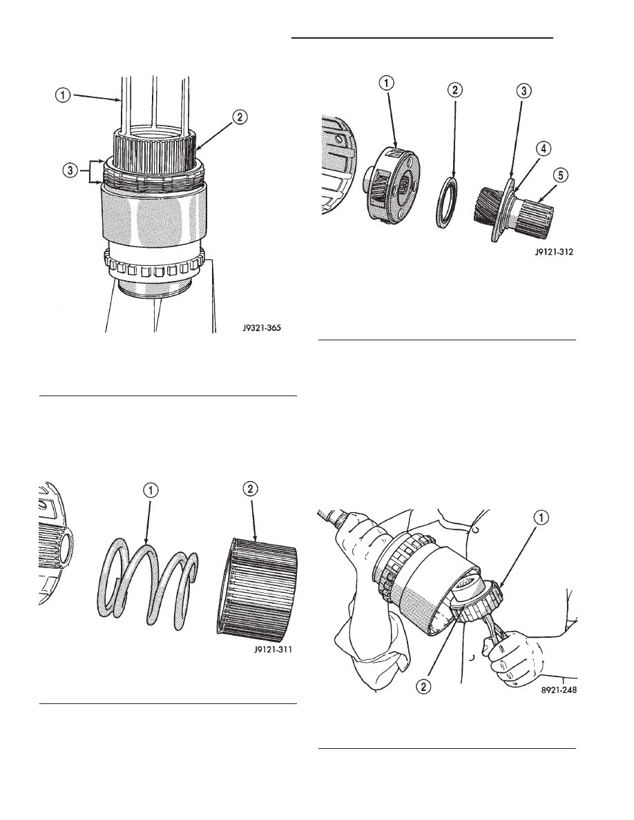
(1) Remove direct clutch hub and spring (Fig. 151).
(2) Remove sun gear and spring plate. Then

remove planetary thrust bearing and planetary gear
(Fig. 152).

(3) Remove

overrunning

clutch

assembly

with

expanding type snap-ring pliers (Fig. 153). Insert pli-
ers into clutch hub. Expand pliers to grip hub splines
and remove clutch with counterclockwise, twisting
motion.

(4) Remove

thrust

bearing

from

overrunning

clutch hub.

(5) Remove overrunning clutch from hub.
(6) Mark position of annulus gear and direct clutch

drum for assembly alignment reference (Fig. 154).
Use small center punch or scriber to make alignment
marks.

Fig. 150 Direct Clutch Pack Removal

1 - SPECIAL TOOL 6227-1
2 - DIRECT CLUTCH HUB
3 - DIRECT CLUTCH PACK

Fig. 151 Direct Clutch Hub And Spring Removal

1 - DIRECT CLUTCH SPRING
2 - DIRECT CLUTCH HUB

Fig. 152 Removing Sun Gear,

Thrust Bearing And Planetary Gear

1 - PLANETARY GEAR
2 - PLANETARY THRUST BEARING
3 - CLUTCH SPRING PLATE
4 - SPRING PLATE SNAP-RING
5 - SUN GEAR

Fig. 153 Overrunning Clutch Assembly Removal/

Installation

1 - OVERRUNNING CLUTCH
2 - NEEDLE BEARING

21 - 352

AUTOMATIC TRANSMISSION - 46RE

AN

OVERDRIVE UNIT (Continued)

(7) Remove direct clutch drum rear retaining ring

(Fig. 155).

(8) Remove direct clutch drum outer retaining ring

(Fig. 156).

(9) Mark annulus gear and output shaft for assem-

bly alignment reference (Fig. 157). Use punch or
scriber to mark gear and shaft.

Fig. 154 Marking Direct Clutch Drum And Annulus

Gear For Assembly Alignment

1 - DIRECT CLUTCH DRUM
2 - HAMMER
3 - PUNCH

Fig. 155 Clutch Drum Inner Retaining Ring Removal

1 - INNER RETAINING RING
2 - DIRECT CLUTCH DRUM
3 - ANNULUS GEAR

Fig. 156 Clutch Drum Outer Retaining Ring Removal

1 - OUTER RETAINING RING

Fig. 157 Marking Annulus Gear And Output Shaft

For Assembly Alignment

1 - OUTPUT SHAFT
2 - HAMMER
3 - PUNCH

AN

AUTOMATIC TRANSMISSION - 46RE

21 - 353

OVERDRIVE UNIT (Continued)

(10) Remove snap-ring that secures annulus gear

on output shaft (Fig. 158). Use two screwdrivers to
unseat and work snap-ring out of groove as shown.

(11) Remove annulus gear from output shaft (Fig.

159). Use rawhide or plastic mallet to tap gear off
shaft.

GEAR CASE AND PARK LOCK

(1) Remove locating ring from gear case.
(2) Remove park pawl shaft retaining bolt and

remove shaft, pawl and spring.

(3) Remove reaction plug snap-ring and remove

reaction plug.

(4) Remove output shaft seal.

CLEANING

Clean the geartrain and case components with sol-

vent. Dry all parts except the bearings with com-
pressed air. Allow bearings to air dry.

Do not use shop towels for wiping parts dry unless

the towels are made from a lint-free material. A suf-
ficient quantity of lint (from shop towels, cloths, rags,
etc.) could plug the transmission filter and fluid pas-
sages.

Discard the old case gasket and seals. Do not

attempt to salvage these parts. They are not reus-
able. Replace any of the overdrive unit snap-rings if
distorted or damaged.

Minor nicks or scratches on components can be

smoothed with crocus cloth. However, do not attempt
to reduce severe scoring on any components with
abrasive materials. Replace severely scored compo-
nents; do not try to salvage them.

INSPECTION

Check condition of the park lock components and

the overdrive case.

Check the bushings in the overdrive case. Replace

the bushings if severely scored or worn. Also replace
the case seal if loose, distorted, or damaged.

Examine the overdrive and direct clutch discs and

plates. Replace the discs if the facing is worn,
severely scored, or burned and flaking off. Replace
the clutch plates if worn, heavily scored, or cracked.
Check the lugs on the clutch plates for wear. The
plates should slide freely in the drum. Replace the
plates or drum if binding occurs.

Check condition of the annulus gear, direct clutch

hub, clutch drum and clutch spring. Replace the gear,
hub and drum if worn or damaged. Replace the
spring if collapsed, distorted, or cracked.

Be sure the splines and lugs on the gear, drum and

hub are in good condition. The clutch plates and
discs should slide freely in these components.

Inspect the thrust bearings and spring plate.

Replace the plate if worn or scored. Replace the bear-
ings if rough, noisy, brinnelled, or worn.

Inspect the planetary gear assembly and the sun

gear and bushings. If either the sun gear or the
bushings are damaged, replace the gear and bush-
ings as an assembly. The gear and bushings are not
serviced separately.

Fig. 158 Annulus Gear Snap-Ring Removal

1 - OUTPUT SHAFT
2 - ANNULUS GEAR
3 - SNAP-RING

Fig. 159 Annulus Gear Removal

1 - OUTPUT SHAFT
2 - ANNULUS GEAR

21 - 354

AUTOMATIC TRANSMISSION - 46RE

AN

OVERDRIVE UNIT (Continued)

The planetary carrier and pinions must be in good

condition. Also be sure the pinion pins are secure and
in good condition. Replace the carrier if worn or dam-
aged.

Inspect the overrunning clutch and race. The race

surface should be smooth and free of scores. Replace
the overrunning clutch assembly or the race if either
assembly is worn or damaged in any way.

Replace the shaft pilot bushing and inner bushing

if damaged. Replace either shaft bearing if rough or
noisy. Replace the bearing snap-rings if distorted or
cracked.

Check the machined surfaces on the output shaft.

These surfaces should clean and smooth. Very minor
nicks or scratches can be smoothed with crocus cloth.
Replace the shaft if worn, scored or damaged in any
way.

Inspect the output shaft bushings. The small bush-

ing is the intermediate shaft pilot bushing. The large
bushing is the overrunning clutch hub bushing.
Replace either bushing if scored, pitted, cracked, or
worn.

ASSEMBLY

GEARTRAIN AND DIRECT CLUTCH

(1) Soak direct clutch and overdrive clutch discs in

Mopar

t ATF +4, type 9602, transmission fluid. Allow

discs to soak for 10-20 minutes.

(2) Install new pilot bushing and clutch hub bush-

ing in output shaft if necessary (Fig. 160). Lubricate
bushings with petroleum jelly, or transmission fluid.

(3) Install

annulus

gear

on

output

shaft,

if

removed. Then install annulus gear retaining snap-
ring (Fig. 161).

(4) Align and install clutch drum on annulus gear

(Fig. 162). Be sure drum is engaged in annulus gear
lugs.

(5) Install clutch drum outer retaining ring (Fig.

162).

Fig. 160 Output Shaft Pilot Bushing

1 - OUTPUT SHAFT HUB
2 - OVERRUNNING CLUTCH HUB BUSHING
3 - INTERMEDIATE SHAFT PILOT BUSHING

Fig. 161 Annulus Gear Installation

1 - SNAP-RING
2 - OUTPUT SHAFT FRONT BEARING
3 - ANNULUS GEAR

Fig. 162 Clutch Drum And Outer Retaining Ring

Installation

1 - ANNULUS GEAR
2 - OUTER SNAP-RING
3 - CLUTCH DRUM

AN

AUTOMATIC TRANSMISSION - 46RE

21 - 355

OVERDRIVE UNIT (Continued)


Content   ..  675  676  677  678   ..