Dodge Dakota (R1). Manual - part 629


  Index      Dodge     Dodge Dakota (R1) - service repair manual 2000 year


Search            


Content   ..  627  628  629  630   ..


Dodge Dakota (R1). Manual - part 629


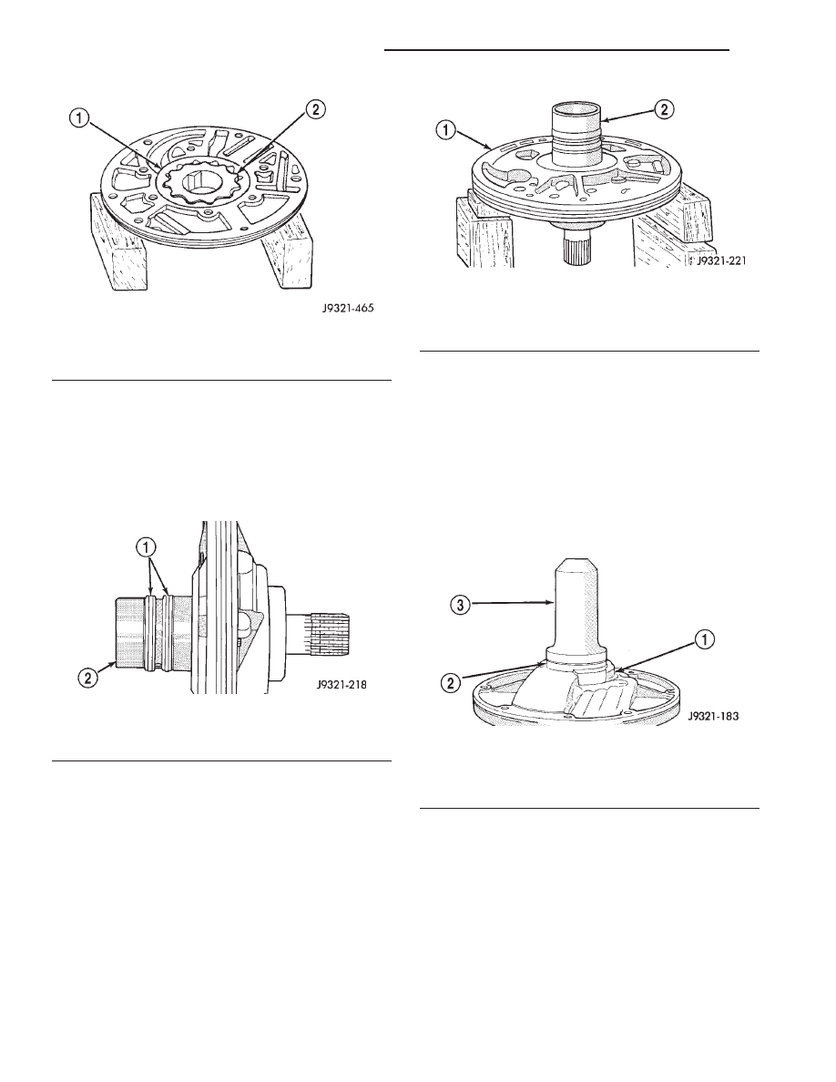
CAUTION: The reaction shaft support seal rings will
break if overspread, or twisted. If new rings are
being installed, spread them only enough for instal-
lation. Also be very sure the ring ends are securely
hooked together after installation. Otherwise, the
rings will either prevent pump installation, or break
during installation.

(8) Install reaction shaft support on pump housing

(Fig. 119).

(9) Align reaction support on pump housing. Use

alignment marks made at disassembly. Or, rotate
support until bolt holes in support and pump housing
are all aligned (holes are offset for one-way fit).

(10) Install all bolts that attach support to pump

housing. Then tighten bolts finger tight.

(11) Tighten support-to-pump bolts to required

torque as follows:

(a) Reverse pump assembly and install it in

transmission case. Position pump so bolts are fac-
ing out and are accessible.

(b) Secure pump assembly in case with 2 or 3

bolts, or with pilot studs.

(c) Tighten support-to-pump bolts to 20 N·m (15

ft. lbs.).

(d) Remove pump assembly from transmission

case.
(12) Install new oil seal in pump with Special Tool

C-4193 and Tool Handle C-4171 (Fig. 120). Be sure
seal lip faces inward.

(13) Install new seal ring around pump housing.

Be sure seal is properly seated in groove.

(14) Lubricate lip of pump oil seal and O-ring seal

with transmission fluid.

OUTPUT SHAFT FRONT
BEARING

REMOVAL

(1) Remove overdrive unit from the vehicle.
(2) Remove overdrive geartrain from housing.
(3) Remove snap-ring holding output shaft front

bearing to overdrive geartrain. (Fig. 121).

(4) Pull bearing from output shaft.

Fig. 117 Pump Inner Gear Installation

1 - OUTER GEAR
2 - INNER GEAR

Fig. 118 Hub Seal Ring Position

1 - SEAL RINGS
2 - SUPPORT HUB

Fig. 119 Assembling Reaction Shaft Support And

Pump Housing

1 - PUMP HOUSING
2 - REACTION SHAFT SUPPORT

Fig. 120 Pump Oil Seal Installation

1 - PUMP BODY
2 - PUMP SEAL
3 - SPECIAL TOOL C-4193

21 - 160

AUTOMATIC TRANSMISSION - 42RE

AN

OIL PUMP (Continued)

INSTALLATION

(1) Place

replacement

bearing

in

position

on

geartrain with locating retainer groove toward the
rear.

(2) Push bearing onto shaft until the snap-ring

groove is visible.

(3) Install snap-ring to hold bearing onto output

shaft.

(4) Install overdrive geartrain into housing.
(5) Install overdrive unit in vehicle.

OUTPUT SHAFT REAR
BEARING

REMOVAL

(1) Remove overdrive unit from the vehicle. (Refer

to 21 - TRANSMISSION/TRANSAXLE/AUTOMATIC/
OVERDRIVE - REMOVAL)

(2) Remove overdrive geartrain from housing.
(3) Remove snap-ring holding output shaft rear

bearing into overdrive housing (Fig. 122).

(4) Using a suitable driver inserted through the

rear end of housing, drive bearing from housing.

INSTALLATION

(1) Place replacement bearing in position in hous-

ing.

(2) Using a suitable driver, drive bearing into

housing until the snap-ring groove is visible.

(3) Install snap-ring to hold bearing into housing

(Fig. 122).

(4) Install overdrive geartrain into housing.

(5) Install overdrive unit in vehicle.

OVERDRIVE CLUTCH

DESCRIPTION

The overdrive clutch (Fig. 123) is composed of the

pressure plate, clutch plates, holding discs, overdrive
piston retainer, piston, piston spacer, and snap-rings.
The overdrive clutch is the forwardmost component
in the transmission overdrive unit and is considered
a holding component. The overdrive piston retainer,
piston, and piston spacer are located on the rear of
the main transmission case.

NOTE: The number of discs and plates may vary
with each engine and vehicle combination.

OPERATION

To apply the clutch, pressure is applied between

the piston retainer and piston. The fluid pressure is
provided by the oil pump, transferred through the
control valves and passageways, and enters the
clutch through passages at the lower rear portion of
the valve body area. With pressure applied between
the piston retainer and piston, the piston moves
away from the piston retainer and compresses the
clutch pack. This action applies the clutch pack,
allowing torque to flow through the intermediate
shaft into the overdrive planetary gear set. The over-
drive clutch discs are attached to the overdrive clutch
hub while the overdrive clutch plates, reaction plate,
and pressure plate are lugged to the overdrive hous-
ing. This allows the intermediate shaft to transfer
the engine torque to the planetary gear and overrun-

Fig. 121 Output Shaft Front Bearing

1 - OUTPUT SHAFT FRONT BEARING
2 - SNAP-RING
3 - OUTPUT SHAFT
4 - GROOVE TO REAR
5 - OVERDRIVE GEARTRAIN

Fig. 122 Output Shaft Rear Bearing

1 - OUTPUT SHAFT REAR BEARING
2 - OVERDRIVE HOUSING
3 - SNAP-RING

AN

AUTOMATIC TRANSMISSION - 42RE

21 - 161

OUTPUT SHAFT FRONT BEARING (Continued)

ning clutch. This drives the planetary gear inside the
annulus, which is attached to the overdrive clutch
drum and output shaft, creating the desired gear
ratio. The waved snap-ring is used to cushion the
application of the clutch pack.

OVERDRIVE SWITCH

DESCRIPTION

The overdrive OFF (control) switch is located in

the shift lever arm (Fig. 124). The switch is a
momentary contact device that signals the PCM to
toggle current status of the overdrive function.

OPERATION

At key-on, overdrive operation is allowed. Pressing

the switch once causes the overdrive OFF mode to be
entered and the overdrive OFF switch lamp to be
illuminated. Pressing the switch a second time
causes normal overdrive operation to be restored and
the overdrive lamp to be turned off. The overdrive
OFF mode defaults to ON after the ignition switch is
cycled OFF and ON. The normal position for the con-
trol switch is the ON position. The switch must be in
this position to energize the solenoid and allow a 3-4
upshift. The control switch indicator light illuminates
only when the overdrive switch is turned to the OFF
position, or when illuminated by the transmission
control module.

DIAGNOSIS AND TESTING - OVERDRIVE
ELECTRICAL CONTROLS

The overdrive off switch, valve body solenoid, case

connectors and related wiring can all be tested with
a 12 volt test lamp or a volt/ohmmeter. Check conti-
nuity of each component when diagnosis indicates
this is necessary.

Switch and solenoid continuity should be checked

whenever the transmission fails to shift into fourth
gear range.

Fig. 123 Overdrive Clutch

1 - REACTION PLATE

2 - PRESSURE PLATE

Fig. 124 Overdrive Off Switch

21 - 162

AUTOMATIC TRANSMISSION - 42RE

AN

OVERDRIVE CLUTCH (Continued)

REMOVAL

(1) Using a plastic trim tool, remove the overdrive

off switch retainer from the shift lever (Fig. 125).

(2) Pull the switch outwards to release it from the

connector in the lever (Fig. 126)

INSTALLATION

NOTE: There is enough slack in the wire to pull out
the connector from the lever.

(1) Pull the connector out of the lever just enough

to grasp it.

CAUTION: Be careful not to bend the pins on the
overdrive off switch. Use care when installing the
switch, as it is not indexed, and can be accidentally
installed incorrectly.

(2) Install the overdrive off switch into the connec-

tor (Fig. 127)

(3) Push the overdrive off switch and wiring into

the shift lever.

(4) Install the overdrive off switch retainer onto

the shift lever.

OVERDRIVE UNIT

REMOVAL

(1) Shift transmission into PARK.
(2) Raise vehicle.
(3) Remove transfer case, if equipped.
(4) Mark propeller shaft universal joint(s) and axle

pinion yoke, or the companion flange and flange
yoke, for alignment reference at installation, if necc-
esary.

(5) Disconnect and remove the rear propeller shaft,

if necessary. (Refer to 3 - DIFFERENTIAL & DRIV-
ELINE/PROPELLER SHAFT/PROPELLER SHAFT -
REMOVAL)

(6) Remove transmission oil pan, remove gasket,

drain oil and reinstall pan.

(7) If overdrive unit had malfunctioned, or if fluid

is contaminated, remove entire transmission. If diag-
nosis indicated overdrive problems only, remove just
the overdrive unit.

(8) Support transmission with transmission jack.

Fig. 125 Overdrive Off Switch Retainer

1 - GEAR SHIFT LEVER
2 - OVERDRIVE OFF SWITCH RETAINER
3 - PLASTIC TRIM TOOL

Fig. 126 Remove the Overdrive Off Switch

1 - GEAR SHIFT LEVER
2 - OVERDRIVE OFF SWITCH

Fig. 127 Install the Overdrive Off Switch

1 - GEAR SHIFT LEVER
2 - OVERDRIVE OFF SWITCH WIRING CONNECTOR
3 - OVERDRIVE OFF SWITCH

AN

AUTOMATIC TRANSMISSION - 42RE

21 - 163

OVERDRIVE SWITCH (Continued)


Content   ..  627  628  629  630   ..