Dodge Dakota (R1). Manual - part 607


  Index      Dodge     Dodge Dakota (R1) - service repair manual 2000 year


Search            


Content   ..  605  606  607  608   ..


Dodge Dakota (R1). Manual - part 607


(5) Fill transmission to bottom edge of fill plug

hole with Mopar Transmission Lubricant.

(6) Install and tighten fill plug to 34 N·m (25 ft.

lbs.).

(7) Check transmission vent. Be sure vent is open

and not restricted.

INSTALLATION

NOTE: If a new transmission is being installed, be
sure to use all components supplied with the new
transmission. For example, if a new shift tower is
supplied with the new transmission, do not re-use
the original shift tower.

(1) Apply light coat of Mopar® high temperature

bearing grease to contact surfaces of following com-
ponents:

• input shaft splines.

• release bearing slide surface of front retainer.

• release bearing bore.

• release fork.

• release fork ball stud.

• propeller shaft slip yoke.
(2) Apply sealer to threads of drain plug, then

install plug in case.

(3) Mount transmission on jack and position trans-

mission under vehicle. Secure transmission to jack
with safety chains.

(4) Raise transmission until input shaft is centered

in clutch disc hub.

(5) Move transmission forward and start input

shaft in clutch disc.

(6) Work transmission forward until seated against

engine. Do not allow transmission to remain unsup-
ported after input shaft has entered clutch disc.

(7) Install and tighten transmission to engine bolts

to 108 N·m (80 ft. lbs.).

(8) Position transmission harness wires in clips on

shift cover.

(9) Install slave cylinder and shield, if equipped.
(10) Install transmission mount on transmission or

rear crossmember.

2WD

(1) Install rear crossmember.

NOTE: Ensure wiring harness is clear before install-
ing crossmember.

(2) Remove transmission jack and engine support

fixture.

(3) Align and install propeller shaft.
(4) Lower vehicle.
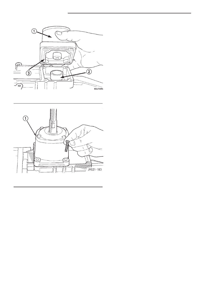
(5) Install shift tower and lever assembly. Tighten

shift tower bolts to 7-10 N·m (5-7 ft. lbs.).

(6) Install shift boot.
(7) Install floor console. Refer to 23 Body for pro-

cedures.

(8) Connect battery negative cable.

4WD

(1) Install transfer case shift lever on transmis-

sion.

(2) Install rear crossmember.

NOTE: Ensure wiring harness is clear before install-
ing crossmember.

Fig. 125 SHIFT TOWER

1 - SHIFT TOWER

Fig. 126 SHIFT TOWER BOLTS

1 - SHIFT TOWER AND LEVER ASSEMBLY

21 - 72

MANUAL - NV3500

AN

MANUAL - NV3500 (Continued)

(3) Remove transmission jack and engine support

fixture.

(4) Install transfer case on transmission jack.

Secure transfer case to jack with safety chains.

(5) Raise jack and align transfer case input gear

with transmission output shaft.

(6) Move transfer case forward and seat it on

transmission.

(7) Install and tighten transfer case attaching

nuts. Tighten nuts to 41-47 N·m (30-35 ft. lbs.) if
case has 3/8 studs, or 30-41 N·m (22-30 ft. lbs.) if
case has 5/16 studs.

(8) Connect backup light switch wires.
(9) Install transmission dust cover.
(10) Install starter.
(11) Install transfer case shift lever to side of

transfer case.

(12) Connect transfer case shift lever to range

lever on transfer case.

(13) Align and connect propeller shafts.
(14) Fill transmission with required lubricant.

Check lubricant level in transfer case and add lubri-
cant if necessary.

(15) Install transfer case skid plate, if equipped,

and crossmember. Tighten attaching bolts/nuts to 41
N·m (30 ft. lbs.).

(16) Install exhaust system components.
(17) Lower vehicle.
(18) Install shift tower and lever assembly. Tighten

shift tower bolts to 7-10 N·m (5-7 ft. lbs.).

(19) Install shift lever boot.
(20) Install floor console. Refer to 23 Body for pro-

cedures.

(21) Connect battery negative cable.

SPECIFICATIONS

SPECIFICATIONS - NV3500

TORQUE SPECIFICATIONS

DESCRIPTION

N·m

Ft. Lbs.

In. Lbs.

Clutch Housing Bolts

54-61

40-45

-

Crossmember Bolts

61-75

45-55

-

Crossmember Insulator

Nuts

54-61

40-45

-

Drain/Fill Plug

9-27

14-20

-

Front to Rear Housing

Bolts

30-35

22-26

-

Front Bearing Bolts

7-10

5-7

62-88

Idler Shaft Bolts

19-25

14-18

-

Rear Bearing Bolts

30-35

22-26

-

Shift Tower Bolts

7-10

5-7

-

Slave Cylinder Nuts

23

17

203

Transfer Case Nuts

47

35

-

AN

MANUAL - NV3500

21 - 73

MANUAL - NV3500 (Continued)

SPECIAL TOOLS

MANUAL - NV3550

Remover Seal C-3985-B

Installer Seal C-3972-A

Remover Bushing 6957

Installer Bushing 6951

Handle C-4171

Remover Plug 8117

Remover/Installer 6858

Fixture 6747

21 - 74

MANUAL - NV3500

AN

MANUAL - NV3500 (Continued)

Adapter 6747-1A

Adapter 6747-2B

Cup Adapter 8115

Splitter Bearing 1130

Tube 6310-1

Installer Bushing 8118

Remover/Installer 8119

Pin Alignment 8120

Installer Seal C-3860-A

Installer 8123

Installer Cone 6448

AN

MANUAL - NV3500

21 - 75

MANUAL - NV3500 (Continued)


Content   ..  605  606  607  608   ..