Dodge Dakota (R1). Manual - part 533


  Index      Dodge     Dodge Dakota (R1) - service repair manual 2000 year


Search            


Content   ..  531  532  533  534   ..


Dodge Dakota (R1). Manual - part 533


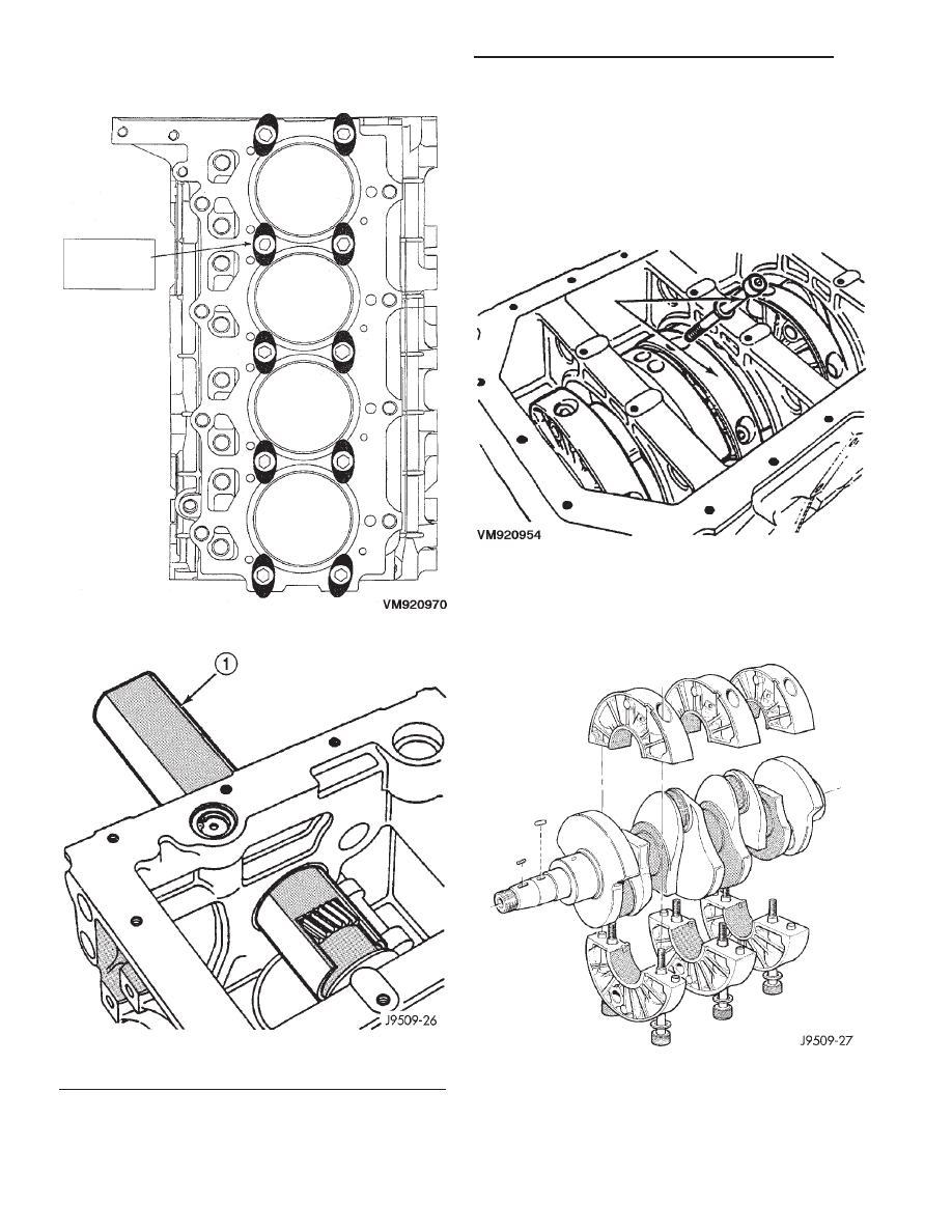
(20) Slide the crankshaft and bearing carriers

rearward to rear of block. If you encounter difficulty
in removing the complete assembly as previously
described, slide the assembly rearward sufficiently to
gain access to the main bearing carrier bolts. Mark
the carriers for assembly and remove the bolts, two
for each carrier (Fig. 65).

(21) Separate the two halves of each carrier,

remove from the crankshaft and temporarily re-as-
semble the carriers (Fig. 66). Withdraw the crank-
shaft through the rear of the crankcase.

Fig. 63 Liner Clamp Location

Fig. 64 Crankshaft Special Tool VM.1004

1 - TOOL

Fig. 65 Crankshaft Support Locator Bolts

Fig. 66 Crankshaft and Carrier Bearing Assembly

9a - 50

ENGINE 2.5L VM DIESEL INTERNATIONAL

R1

CRANKSHAFT MAIN BEARINGS (Continued)

INSTALLATION

(1) Fit the main bearing supports together. Torque

to 44 N·m (32 ft. lbs.).

(2) Check internal diameter of bearings.
(3) If internal diameter of original bearing is being

checked and figures are not within specifications,
new bearings must be used.

(4) Check the crankshaft main bearing journals to

bearing clearances. Clearances of main bearings is
.03 to .088mm (.0011 to .0035 in.).

NOTE: Assemble engine according to sequence
described, thus saving time and preventing dam-
ages to engine components. Clean parts with a suit-
able solvent and dry them with compressed air
before assembly. Use new gaskets where applicable
and torque wrenches for correct tightening of com-
ponents.

(5) Thoroughly clean crankcase and oil passages,

and blow dry with compressed air.

(6) Install new main bearing shells in each of the

carrier halves. Assemble the carriers to the crank-
shaft

journals,

ensuring

that

the

carriers

are

installed in their original locations and that the pis-
ton jet notch is towards the front of the crank-
shaft
. Secure each carrier with the two bolts
tightening evenly to 44 N·m (32 ft. lbs.). Check that
the oil jet is in position (Fig. 66).

(7) Slide special tool VM.1004 over the crankshaft

gear and, insert the crankshaft and carrier assembly
into the crankcase in the same manner used for
removal.

(8) Align the holes in the lower supports, with the

center of the crankcase webs (Fig. 67).

(9) Secure each support assembly to the crankcase

with the main bearing oil feed and support locators.
Torque to 54 N·m (40 ft. lbs).

(10) Install the rear main bearing support onto

crankshaft ensuring arrow on bearing support aligns
with vertical web in center of crankcase.

(11) Install the rear oil seal.
(12) Install the new O-rings in adaptor plate.
(13) Install the adaptor plate to block. Torque nuts

to 26.5 N·m (20 ft. lbs.).

(14) Install the Allen bolts through adaptor plate

to rear main bearing support. Torque to 11 N·m (97
in. lbs.).

(15) Position the flywheel and O-ring on crank-

shaft and align bolt holes.

NOTE: For purposes of checking crankshaft end
play, used flywheel bolts may be used. Final assem-
bly requires new flywheel bolts.

(16) Install 2 flywheel bolts, 180° apart, and

tighten bolts to 20 N·m plus 60° (15 ft. lbs.) plus 60°.

(17) Attach dial indicator to engine block.
(18) Move crankshaft toward front of engine and

zero indicator.

(19) Move crankshaft toward the rear of engine

and record measurement.

(20) Subtract specified crankshaft end play from

figure obtained. Crankshaft end play .153 to .304mm
(.0060 to .0119 in.).

(21) Select thrust washers which will give correct

end play.

(22) Remove tools and flywheel.
(23) Lubricate thrust washer halves and fit them

into the rear main bearing carrier.

(24) Ensure that crankshaft end and flywheel mat-

ing surfaces are clean and dry. Install

88O’’ ring in

flywheel groove.

(25) To verify correct end play, install 2 flywheel

bolts 180° apart, and tighten bolts to 20 N·m plus 60°
(15 ft. lbs. plus 60°).

(26) Measure crankshaft end play with a dial

gauge. Crankshaft end play should not exceed .153 to
.304mm (.0060 to .0119 in.) (Fig. 68).

CAUTION: Use NEW flywheel bolts for the following
procedure.

(27) Install a new O-ring on flywheel. Install fly-

wheel on crankshaft. The 6 flywheel bolts must be
tightened as follows:

(a) Lubricate and install the 6 new flywheel

bolts.

(b) Torque the 6 flywheel bolts to 49 N·m (36 ft.

lbs.) starting one bolt and following with the oppo-

Fig. 67 Main Bearing Support Alignment

R1

ENGINE 2.5L VM DIESEL INTERNATIONAL

9a - 51

CRANKSHAFT MAIN BEARINGS (Continued)

site one (cross tightening) until completion, in a
clockwise direction.

(c) Loosen one bolt at a time and tighten to 19.6

N·m (14 ft. lbs.) plus 75° using the cross tightening
method.
(28) Install the pistons and connecting rod assem-

blies (Refer to 9 - ENGINE/ENGINE BLOCK/PIS-
TON & CONNECTING ROD - INSTALLATION).

(29) Install the oil pick up tube. Torque bolts to 25

N·m (18 ft. lbs.).

(30) Install the oil pan (Refer to 9 - ENGINE/LU-

BRICATION/OIL PAN - INSTALLATION).

(31) Install the vacuum pump, being careful to

align the gear timing marks with those on the crank-
shaft gear. Torque screws to 20 N·m (15 ft. lbs.).

(32) Before installing the oil pump check pump

bore depth in block (A) and pump body height (B)
(Fig. 69). Difference between A and B should be
0.020-0.082 mm (.0007 to 0032 in.).

(33) Install the oil pump. Torque screws to 27 N·m

(20 ft. lbs.). Check for normal backlash between
pump and crankshaft gears.

(34) Install the timing gear cover (Refer to 9 -

ENGINE/VALVE TIMING/TIMING BELT / CHAIN
COVER(S) - INSTALLATION).

(35) Install the vibration damper (Refer to 9 -

ENGINE/ENGINE BLOCK/VIBRATION DAMPER -
INSTALLATION)

(36) Install the cylinder heads (Refer to 9 -

ENGINE/CYLINDER HEAD - INSTALLATION).

(37) Install the rocker arms and push rods (Refer

to 9 - ENGINE/CYLINDER HEAD/ROCKER ARMS -
INSTALLATION).

(38) Install the cylinder head cover (Refer to 9 -

ENGINE/CYLINDER

HEAD/CYLINDER

HEAD

COVER(S) - INSTALLATION).

(39) Install the accessary drive system.
(40) Install the engine in vehicle (Refer to 9 -

ENGINE - INSTALLATION).

(41) Fill engine with the correct amount of fluids

specified.

(42) Connect the negative battery cable.

HYDRAULIC LIFTERS (CAM IN
BLOCK)

DISASSEMBLY - HYDRAULIC TAPPETS

(1) Pry out plunger retainer spring clip.
(2) Clean varnish deposits from inside of tappet

body above plunger cap.

(3) Invert tappet body and remove plunger cap,

plunger, check valve, check valve spring, check valve
retainer and plunger spring. Check valve could be
flat or ball.

ASSEMBLY - HYDRAULIC TAPPETS

(1) Clean all tappet parts in a solvent that will

remove all varnish and carbon.

(2) Replace tappets that are unfit for further ser-

vice with new assemblies.

(3) If plunger shows signs of scoring or wear,

install a new tappet assembly. If valve is pitted, or
valve seat on end of plunger is prevented from seat-
ing, install a new tappet assembly.

(4) Assemble tappets.

Fig. 68 Measuring Crankshaft End Play

Fig. 69 Oil Pump Bore Depth

9a - 52

ENGINE 2.5L VM DIESEL INTERNATIONAL

R1

CRANKSHAFT MAIN BEARINGS (Continued)

OIL PUMP

REMOVAL

(1) Disconnect the negative battery cable.
(2) Remove the timing gear cover (Refer to 9 -

ENGINE/VALVE TIMING/TIMING BELT / CHAIN
COVER(S) - REMOVAL).

(3) Remove the oil pump (Fig. 70).

CLEANING

Wash all parts in a suitable solvent and inspect

carefully for damage or wear (Fig. 72).

INSPECTION

(1) Before installing oil pump check pump bore

depth in block (A) and pump body height (B) (Fig.
71).

Difference

between

A

and

B

should

be

0.020-0.082 mm.

(2) Check clearance between rotors (Fig. 73).

INSTALLATION

(1) Install new O-ring and lubricate with clean

engine oil.

(2) Install the oil pump. Torque screws to 27.5 N·m

(20 ft. lbs.). Check for normal backlash between
pump and crankshaft gears.

(3) Install the timing gear cover (Refer to 9 -

ENGINE/VALVE TIMING/TIMING BELT / CHAIN
COVER(S) - INSTALLATION).

Fig. 70 Oil Pump Removal

1 - CAMSHAFT GEAR
2 - CRANKSHAFT GEAR
3 - OIL PUMP
4 - VACUUM PUMP

Fig. 71 Oil Pump Bore Depth

Fig. 72 Oil Pump Inner and Outer Rotors

1 - OUTER ROTOR
2 - INNER ROTOR

R1

ENGINE 2.5L VM DIESEL INTERNATIONAL

9a - 53


Content   ..  531  532  533  534   ..