Dodge Dakota (R1). Manual - part 495


  Index      Dodge     Dodge Dakota (R1) - service repair manual 2000 year


Search            


Content   ..  493  494  495  496   ..


Dodge Dakota (R1). Manual - part 495


CAUTION: The bedplate to cylinder block mateing
surface must be coated with sealant prior to instal-
lation. Failure to do so will cause severe oil leaks.

NOTE: The installation time to install the bedplate
after the sealant has been applied is critical.

NOTE: Make sure that the bedplate and cylinder
block sealing surfaces are clean and free of oil or
other contaminants. Contaminants on the sealing
surfaces may cause main bearing distortion and/or
oil leaks.

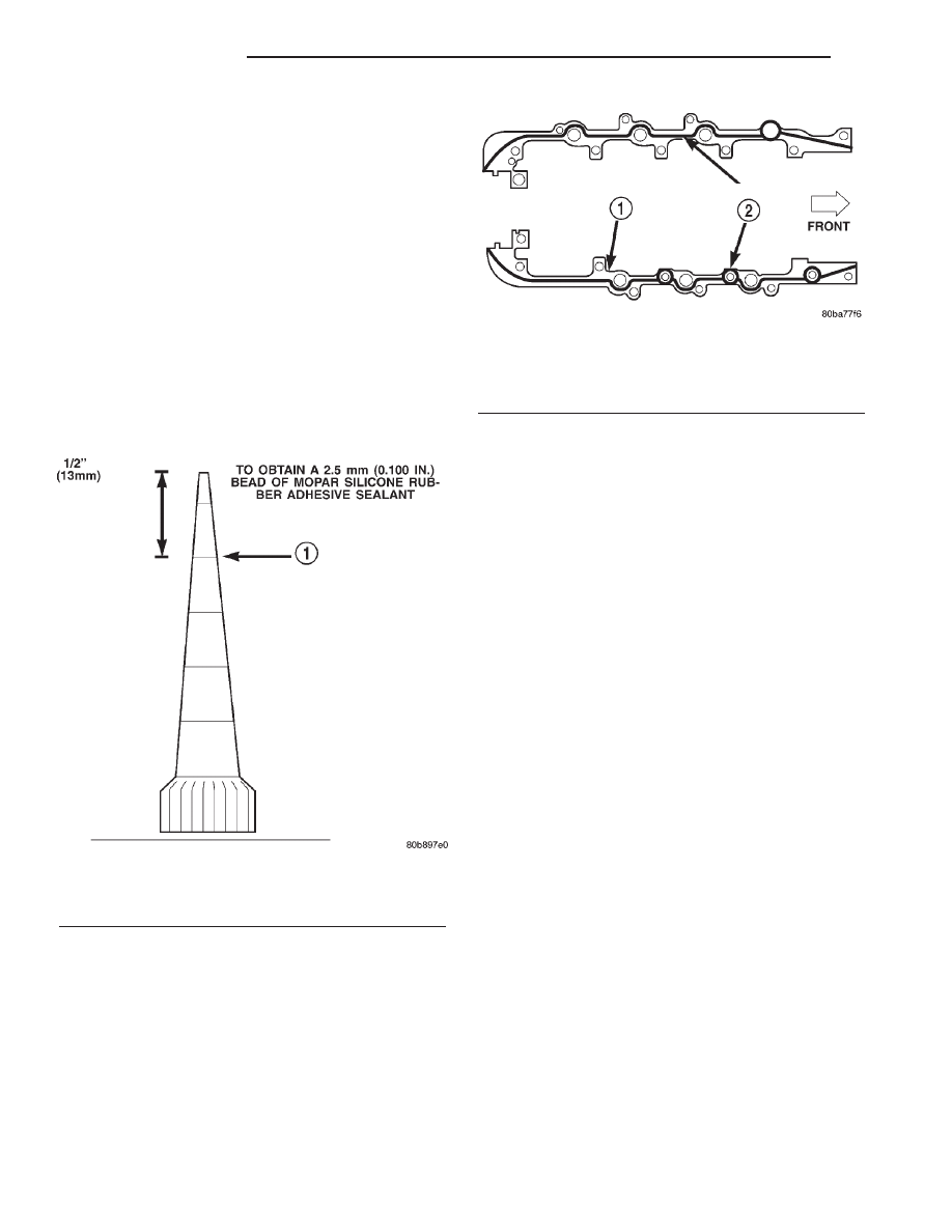
(5) Apply a 2.5mm (0.100 inch) (Fig. 59) bead of

Mopar

t Gen II Silicone Rubber Adhesive sealant to

the cylinder block-to-bedplate mating surface as
shown (Fig. 60).

(6) Coat the crankshaft main bearing journals

with clean engine oil and position the bedplate onto
the cylinder block.

NOTE: Lubricate the bedplate retaining bolts with
clean engine oil prior to installation.

(7) Install the bedplate retaining bolts, making

sure to place the stud bolts in the correct location,
Torque the bolts in the sequence shown (Fig. 61).

• Tighten bolts A – L to 54 N·m (40 ft. lbs.)

• Tighten bolts 1–10 to 2.8 N·m (25 in. lbs.)

• Turn bolts 1–10 an additional 90°.

• Tighten bolts A1– A6 to 27 N·m (20 ft. lbs.)
(8) Measure crankshaft end play. (Refer to 9 -

ENGINE/ENGINE BLOCK/CRANKSHAFT - STAN-
DARD PROCEDURE).

(9) Install the connecting rods and measure side

clearance. (Refer to 9 - ENGINE/ENGINE BLOCK/
CONNECTING

ROD

BEARINGS

-

STANDARD

PROCEDURE).

(10) Position the oil pan gasket/windage tray,

using a new o-ring, install the oil pickup tube.
Torque the bolt to 28N·n (20 ft. lbs.) torque the nuts
to 28N·m (20 ft. lbs.).

(11) Install the oil pan. Torque the retaining bolts

to 15 N·m (11 ft. lbs.) in the sequence shown (Fig.
62).

(12) Install the engine (Refer to 9 - ENGINE -

INSTALLATION).

Fig. 59 Cutting Aplicator to Achieve 2.5mm (0.100

in.) Bead

1 - CUT HERE

Fig. 60 Cylinder Block-to-Bedplate Sealent Bead

Location

1 - CYLINDER BLOCK
2 - SEALANT BEAD LOCATION

9 - 168

ENGINE 4.7L

AN

CRANKSHAFT (Continued)

CRANKSHAFT MAIN
BEARINGS

STANDARD PROCEDURE—CRANKSHAFT MAIN
BEARING - FITTING

MAIN BEARING JOURNAL DIAMETER
(CRANKSHAFT REMOVED)

Crankshaft removed from the cylinder block.
Clean the oil off the main bearing journal.

Determine the maximum diameter of the journal

with a micrometer. Measure at two locations 90°
apart at each end of the journal.

The maximum allowable taper is 0.008mm (0.0004

inch.) and maximum out of round is 0.005mm (0.002
inch). Compare the measured diameter with the jour-
nal diameter specification (Main Bearing Fitting
Chart). Select inserts required to obtain the specified
bearing-to-journal clearance.

CRANKSHAFT MAIN BEARING SELECTION

The main bearings are “select fit” to achieve proper

oil clearances. For main bearing selection, the crank-
shaft position sensor target wheel has grade identifi-
cation marks stamped into it (Fig. 63). These marks
are read from left to right, corresponding with jour-
nal number 1, 2, 3, 4 and 5. The crankshaft position
sensor target wheel is mounted to the number 8
counter weight on the crankshaft.

NOTE: Service main bearings are coded. These
codes identify what size (grade) the bearing is.

Fig. 61 Bedplate Tightening Sequence

1 - BEDPLATE

2 - CYLINDER BLOCK

Fig. 62 Oil Pan Tightening Sequence

AN

ENGINE 4.7L

9 - 169

CRANKSHAFT (Continued)

MAIN BEARING SELECTION CHART—4.7L

GRADE

SIZE mm

(in.)

FOR USE WITH

MARKING

JOURNAL SIZE

A

0.008 mm

U/S

63.488–63.496 mm

(0.0004 in.)

U/S

(2.4996–2.4999 in.)

B

NOMINAL

63.496–63.504 mm

(2.4999–2.5002 in.)

C

0.008 mm

O/S

63.504–63.512 mm

(0.0004 in.)

O/S

(2.5002–2.5005 in.)

INSPECTION

Wipe the inserts clean and inspect for abnormal

wear patterns and for metal or other foreign material
imbedded in the lining. Normal main bearing insert
wear patterns are illustrated (Fig. 64).

NOTE: If any of the crankshaft journals are scored,
the crankshaft must be repaired or replaced.

Inspect the back of the inserts for fractures, scrap-

ings or irregular wear patterns.

Inspect the upper insert locking tabs for damage.

Replace all damaged or worn bearing inserts.

CRANKSHAFT OIL SEAL -
FRONT

REMOVAL

(1) Disconnect negative cable from battery.
(2) Remove accessory drive belt (Refer to 7 -

COOLING/ACCESSORY

DRIVE/DRIVE

BELTS

-

REMOVAL).

(3) Remove A/C compressor mouning fasteners and

set aside.

(4) Drain cooling system (Refer to 7 - COOLING -

STANDARD PROCEDURE).

(5) Remove upper radiator hose.
(6) Disconnect electrical connector for fan mounted

inside radiator shroud.

(7) Remove radiator shroud attaching fasteners.

NOTE: Transmission cooler line snaps into shroud
lower right hand corner.

(8) Remove radiator cooling fan and shroud (Refer

to

7

-

COOLING/ENGINE/RADIATOR

FAN

-

REMOVAL).

(9) Remove crankshaft damper bolt.
(10) Remove damper using Special Tools 8513

Insert and 1026 Three Jaw Puller (Fig. 65).

(11) Using Special Tool 8511, remove crankshaft

front seal (Fig. 66).

Fig. 63 Main Bearing Markings on Target Wheel

1 - REARMOST CRANKSHAFT COUNTER WEIGHT
2 - TARGET WHEEL
3 - MAIN BEARING SELECT FIT MARKINGS

Fig. 64 Main Bearing Wear Patterns

1 - UPPER INSERT
2 - NO WEAR IN THIS AREA
3 - LOW AREA IN BEARING LINING
4 - LOWER INSERT

9 - 170

ENGINE 4.7L

AN

CRANKSHAFT MAIN BEARINGS (Continued)

INSTALLATION

CAUTION: To prevent severe damage to the Crank-
shaft, Damper or Special Tool 8512, thoroughly
clean the damper bore and the crankshaft nose
before installing Damper.

(1) Using Special Tool 8348 and 8512, install

crankshaft front seal (Fig. 67).

(2) Install vibration damper (Refer to 9 - ENGINE/

ENGINE BLOCK/VIBRATION DAMPER - INSTAL-
LATION).

(3) Install radiator cooling fan and shroud (Refer

to

7

-

COOLING/ENGINE/RADIATOR

FAN

-

INSTALLATION).

(4) Install upper radiator hose.
(5) Install A/C compressor and tighten fasteners to

54 N·m (40 ft. lbs.).

(6) Install accessory drive belt refer (Refer to 7 -

COOLING/ACCESSORY

DRIVE/DRIVE

BELTS

-

INSTALLATION).

(7) Refill cooling system (Refer to 7 - COOLING -

STANDARD PROCEDURE).

(8) Connect negative cable to battery.

Fig. 65 Crankshaft Damper—Removal

1 - SPECIAL TOOL 8513 INSERT
2 - SPECIAL TOOL 1026

Fig. 66 Crankshaft Front Seal—Removal

1 - SPECIAL TOOL 8511

Fig. 67 Crankshaft Front Seal—Installation

1 - TIMING CHAIN COVER
2 - SPECIAL TOOL 8348
3 - SPECIAL TOOL 8512

AN

ENGINE 4.7L

9 - 171

CRANKSHAFT OIL SEAL - FRONT (Continued)


Content   ..  493  494  495  496   ..